

Scanning probe apparatus
a probe apparatus and scanning technology, applied in the direction of mechanical measurement arrangements, mechanical roughness/irregularity measurements, instruments, etc., can solve the problems of affecting the scanning stage, so as to reduce the cost of time and effort.
- Summary
- Abstract
- Description
- Claims
- Application Information
AI Technical Summary
Benefits of technology
Problems solved by technology
Method used
Image

Examples
embodiment 1
[0054] In Embodiment 1, the present invention is applied so as to constitute a replaceable scanning stage used in a scanning probe apparatus.
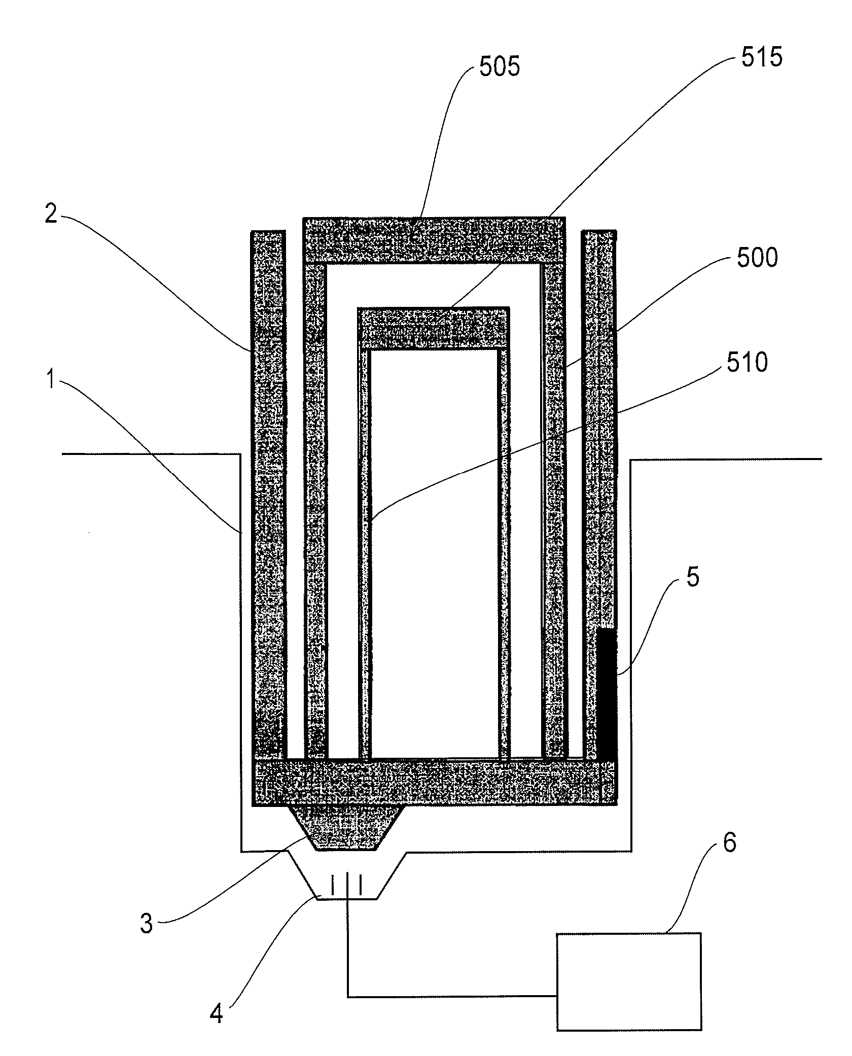
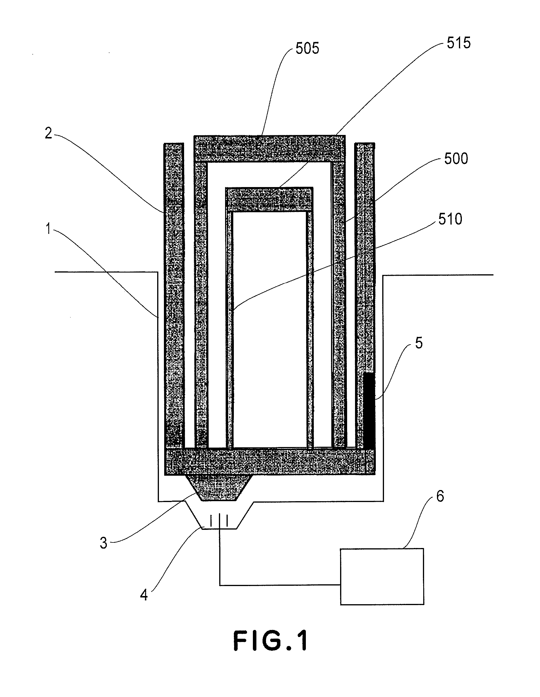
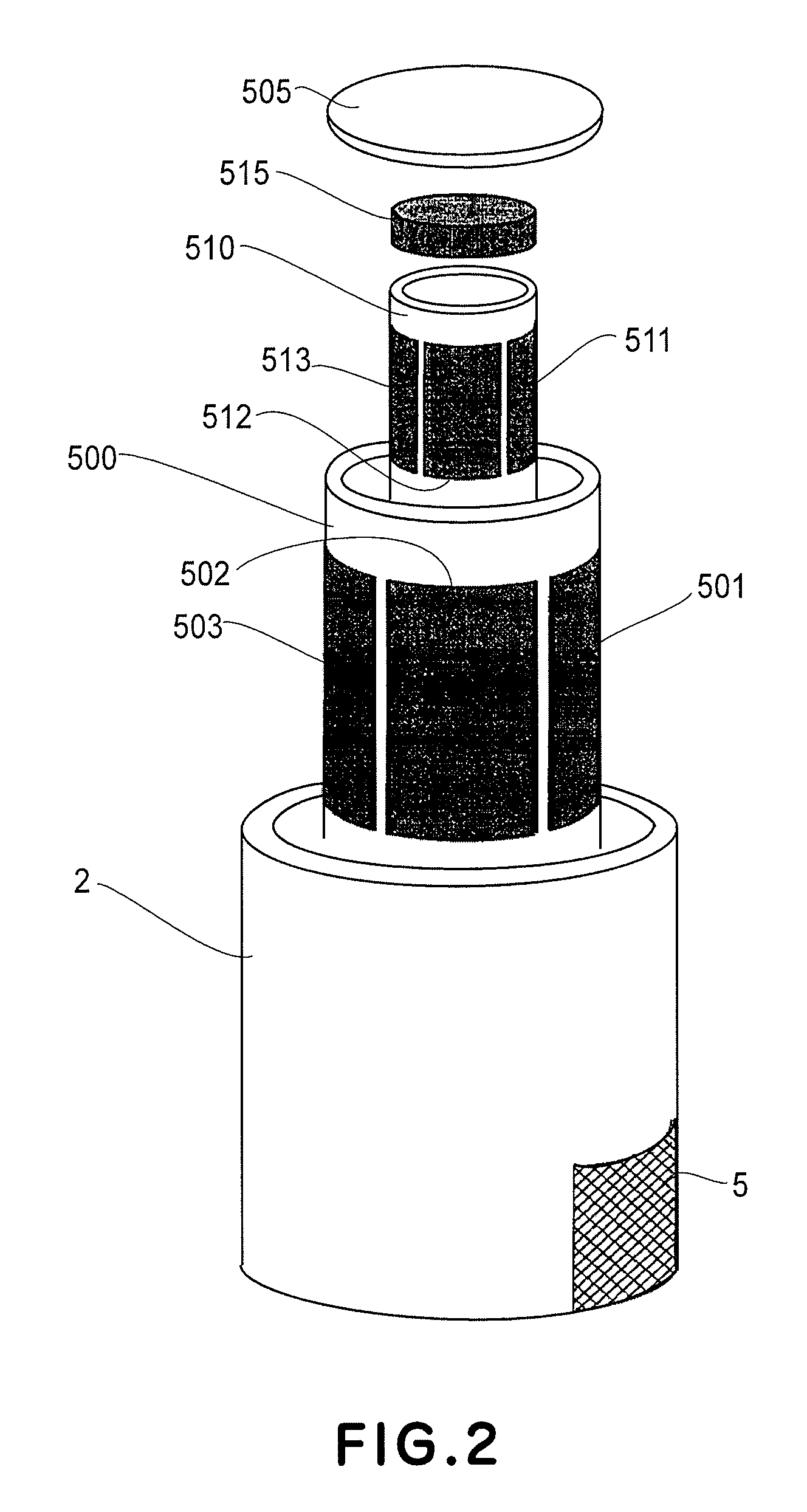
[0055]FIG. 1 is a schematic sectional view of a scanning stage which is replaceable with respect to a main assembly of a scanning probe apparatus in this embodiment. FIG. 2 is a schematic view for illustrating the constitution of the scanning stage used in the scanning probe apparatus illustrating the constitution of the scanning stage used in the scanning probe apparatus in this embodiment.
[0056] Referring to FIGS. 1 and 2, the scanning probe apparatus includes a recess 1 provided to a main assembly of the scanning probe apparatus; a bottom supporting table 2; an electric connector 3 provided to the bottom supporting table; an electric connector 4, to be connected to the electric connector 3, provided at the recess of the main assembly of the scanning probe apparatus; a drive circuit 5 for driving a scanning piezoelectric element and a count...
embodiment 2
[0073] In Embodiment 2, a replaceable scanning mechanism which is different from that in Embodiment 1 and is usable in the scanning probe apparatus of the present invention will be described.
[0074]FIG. 4 and FIG. 5(a) to 5(c) are schematic views showing a constitution of the scanning mechanism in this embodiment.
[0075] In these figures, a scanning mechanism 400 includes a scanning mechanism holding table 401, a drive element base 402, drive elements 403, 404 and 405, drive element holding members 406 and 407, a sample holding member 408, a weight member 409, and a drive circuit 410 for driving the scanning piezoelectric element and the counter piezoelectric element.
[0076] In this embodiment, at an outer portion of the drive element base 402, an IC chip including the drive circuit 410 is provided as shown in FIGS. 4 and 5(a), so that these members are integrally replaceable from the scanning mechanism holding table 401 on the main assembly side of the scanning probe apparatus. Mor...
embodiment 3
[0082] In Embodiment 3, a constitution of a scanning probe apparatus including a probe drive stage and a sample stage both of which are provided with a drive circuit will be described. In this embodiment, as the sample stage, a sample stage having the same constitution as that in Embodiment 1 is used.
[0083] Further, to the probe drive stage, a basic constitution of the sample stage in Embodiment 1 is also applied so as to constitute such a probe drive stage that it is provided with a drive element for moving a probe holding table and a movable portion for cancelling inertial force generated during movement of the probe holding table. Further, the probe drive stage is constituted so that the movable portion and the drive element including the probe holding stage are integrally replaceable from the main assembly of the scanning probe apparatus.
[0084]FIG. 6 is a schematic view for illustrating a constitution of the scanning probe apparatus in this embodiment.
[0085] Referring to FIG....
PUM
| Property | Measurement | Unit |
|---|---|---|
| scanning frequency | aaaaa | aaaaa |
| frequency | aaaaa | aaaaa |
| frequency | aaaaa | aaaaa |
Abstract
Description
Claims
Application Information