System and method for fusibly linking batteries

a technology of fusible linking and batteries, applied in the direction of battery/fuel cell control arrangement, cell components, electric devices, etc., can solve the problems of lack of electrical protection, time-consuming and prone to failure, and difficult to test the connection between each battery and the conductor, etc., and achieve the effect of easy repair

Active Publication Date: 2007-08-16
TESLA INC
View PDF8 Cites 115 Cited by
  • Summary
  • Abstract
  • Description
  • Claims
  • Application Information

AI Technical Summary

Benefits of technology

[0009] A system and method uses conventional wire bonding techniques to wire bond the batteries to the conductors. The wire bonds are constructed of wire that allows for the expected current to pass through the wire bonds without significant heating of the wires due to the current, while allowing the wires bonds to break in an overcurrent condition, such as would be expected during a short circuit. In an overcurrent condition, the wires will break sufficiently to ensure that no arcing will occur at the voltage expected in a worst case short, such as a short between the first conductor and the last conductor in the series of smaller sets. A conventional fuse is inserted in series with the sets of batteries that have series connections between the sets. The conventional fuse will blow at a smaller current than the sum of the wire bonds in each set, to help ensure that the fuse will blow before the wire bonds in the event of an external short circuit, making it easy to repair this condition by replacing a single fuse, rather than requiring repair of all of the wire bonds or replacement of all the sets.

Problems solved by technology
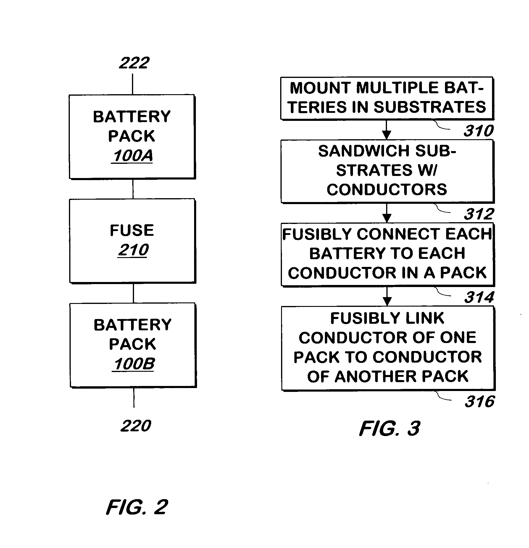
However, there are problems with this approach.
The welding process is time consuming and prone to failure.
It is also difficult to test the connection between each battery and the conductors.
Another problem with this approach is the lack of electrical protection.
A single battery can internally short, due to a malfunction or damage.
Because rechargeable batteries can overheat and explode when short circuited, a short circuit can be catastrophic, not only to the batteries being shorted, but to the other batteries as well, because these non-shorted batteries can be overheated to the point at which they will overheat and explode.
Because batteries can overheat and explode as a result of a short circuit, a major short circuit can cause the failure of one or more of the smaller sets of batteries.

Method used


Image

  • System and method for fusibly linking batteries
  • System and method for fusibly linking batteries

Examples


Embodiment Construction

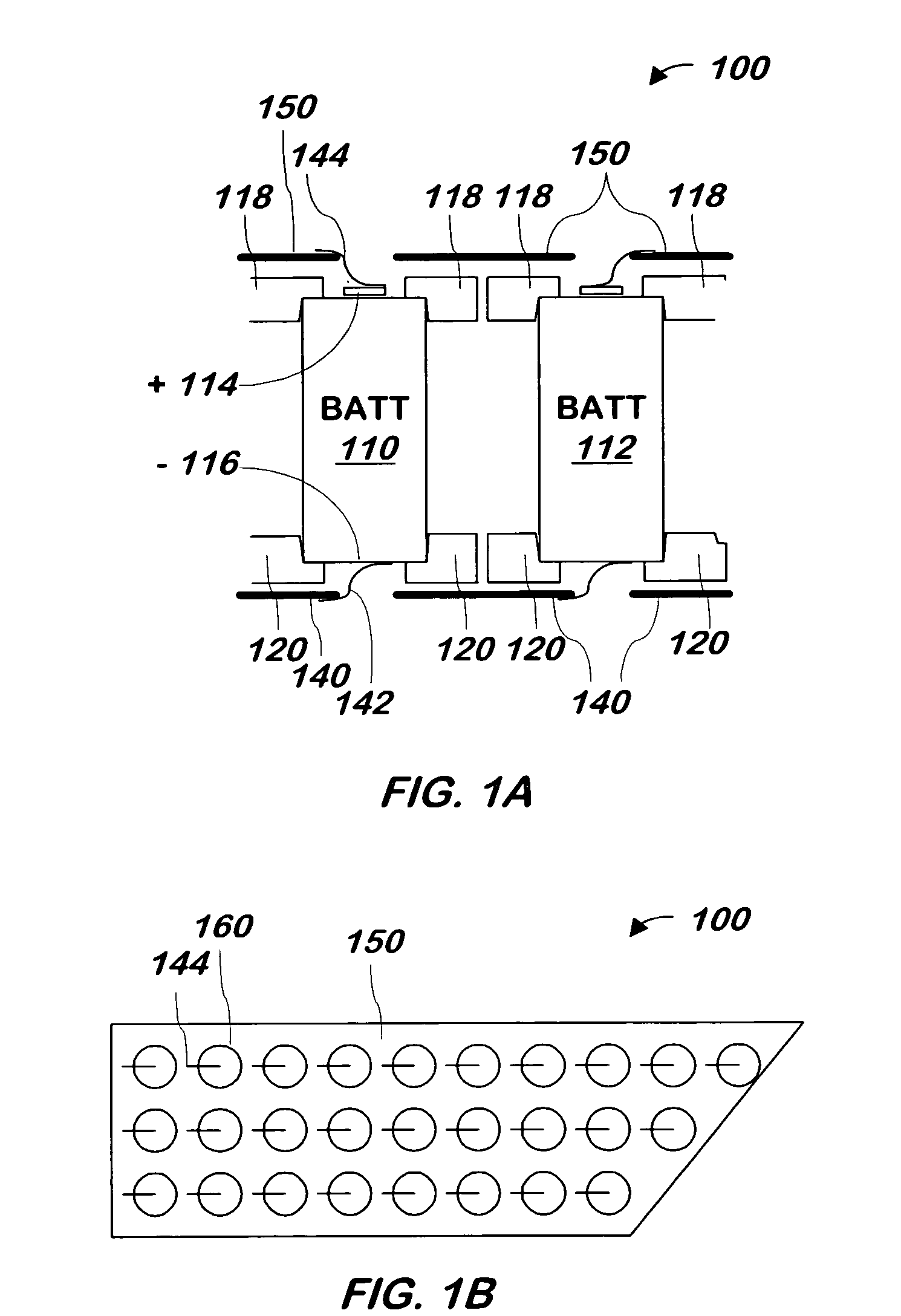
[0014]FIG. 1A is a side view of a portion of battery pack 100 according to one embodiment of the present invention. Referring now to FIG. 1A, batteries 110 and 112 are conventional rechargeable batteries such as Lithium-ion or Nickel metal hydride batteries. Substrate 118 and substrate 120, in which the batteries are mounted, are described in the related application. Conductor 150 and conductor 140 are sheets of hole-punched copper layered over the substrates 118, 120, with holes in each conductor aligned over the ends of each battery. Substrates 118 and 120 serve to hold the batteries and prevent the batteries' positive and negative terminals from touching conductors 150 and 140, respectively.

[0015] The batteries' positive terminals 114 are connected to conductor 150 by fusible links, such as wire bonds 144, and the batteries' negative ends 116 are connected to conductor 140 by similar fusible links, such as wire bonds 142 via holes in the substrates 118, 120 and conductors 140, 1...


PUM

PropertyMeasurementUnit
current carrying capacityaaaaaaaaaa
currentaaaaaaaaaa
polarityaaaaaaaaaa

Abstract

A system and method links batteries in parallel to conductors using wire bonds that act as fuses in the event of an overcurrent condition in a battery. To protect the wire bonds in the case of a larger overcurrent condition, a fuse may be added in series to the parallel batteries.

Description

FIELD OF THE INVENTION [0001] The present invention is related to rechargeable battery systems for energy-conserving electric and hybrid automobiles and more specifically to systems for interconnecting batteries. BACKGROUND OF THE INVENTION [0002] Multiple conventional rechargeable batteries such as Lithium-ion or Nickel metal hydride batteries may be arranged in series or parallel to obtain any desired voltage or current. For example, a set of batteries may be arranged in parallel by sandwiching the batteries between two conductors to obtain a desired current. Many of the parallel sets may be coupled in series to obtain a desired voltage of the larger set. The larger set may be electrically coupled in series or parallel with other similarly sized sets to obtain an even higher voltage or current. [0003] The related application describes one method of managing the electrical connections in the smaller sets of batteries, in which multiple batteries are sandwiched in parallel between t...

Claims


Application Information

Patent Timeline
Patent Type & Authority Applications(United States)
IPC IPC(8): H02J7/00H01M50/529H01M50/51H01M50/514H01M50/522H01M50/583
CPCH01M2/202H01M2/34B60L3/0046B60L3/0069B60L3/04Y10T29/49108B60L2240/549Y02T10/7005Y02T10/7061Y02T10/7011B60L11/1864B60L58/21Y02T10/70Y02E60/10H01M50/522H01M50/514H01M50/583H01M50/51
Inventor STRAUBEL, JEFFREY B.LYONS, DAVIDBERDICHEVSKY, EUGENEKOHN, SCOTTTEIXEIRA, RYAN
Owner TESLA INC
Why Eureka
Try Eureka