Magnetic ratchet for input device roller

Inactive Publication Date: 2007-08-16
LOGITECH EURO SA
View PDF27 Cites 28 Cited by
  • Summary
  • Abstract
  • Description
  • Claims
  • Application Information

AI Technical Summary

Benefits of technology

[0013] The present invention provides a reduced power magnetic or electromagnetic ratchet for a roller on an input device. In one embodiment, opposing rings of permanent magnets are mounted in the roller, or are attached to the roller by a gearing arrangement. This eliminates

Problems solved by technology

A disadvantage of force feedback is the power required to provide the force which is felt by the user.
This is particularly problematic for a cord

Method used


Image

  • Magnetic ratchet for input device roller
  • Magnetic ratchet for input device roller
  • Magnetic ratchet for input device roller

Examples


Example

System Overview

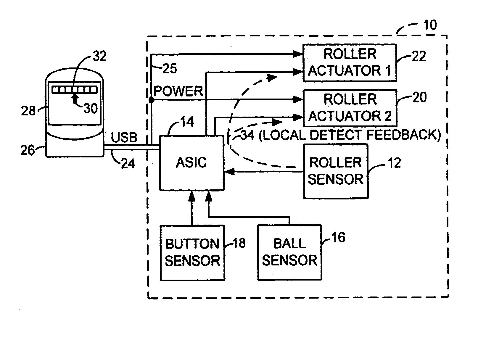
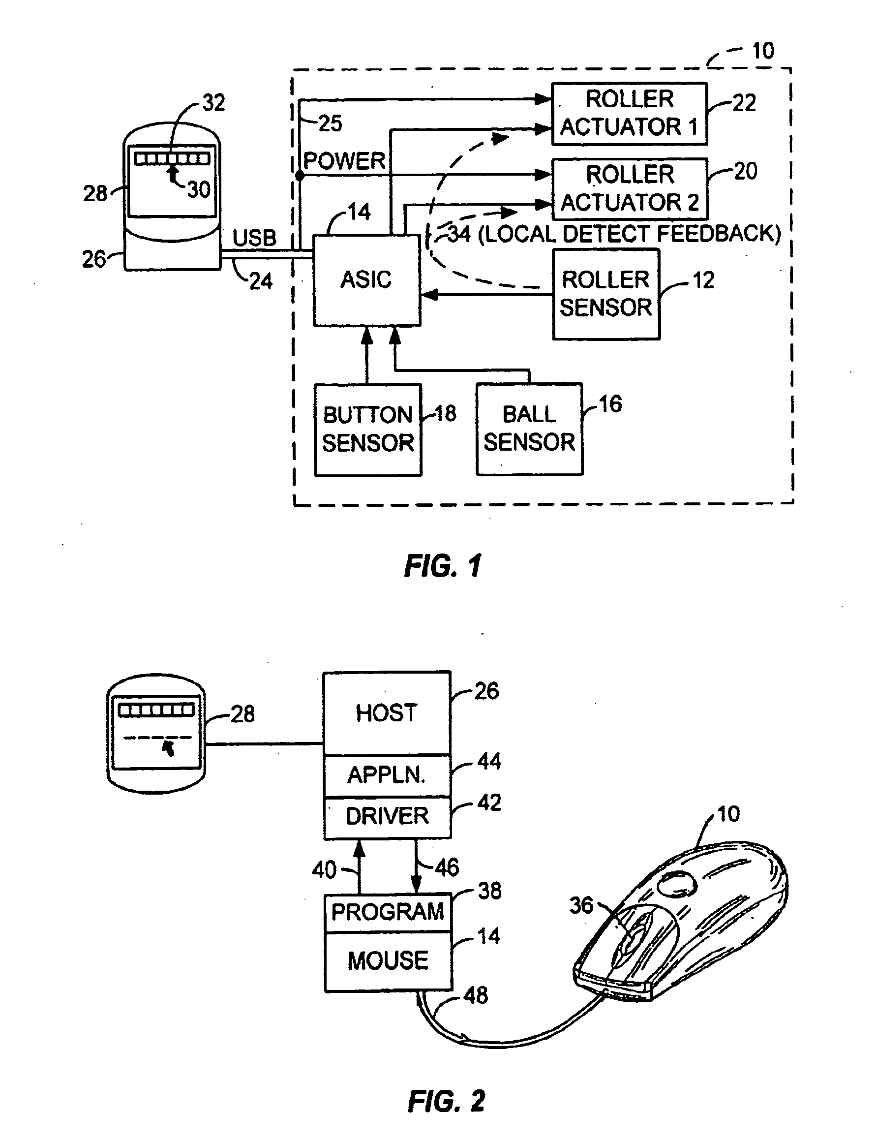
[0022]FIG. 1 is a block diagram of the electronic system for tactile feedback according to an embodiment of the invention. Shown is a mouse 10 which has a roller sensor 12 for detecting the movement of a roller or wheel. The sensor signals are provided to a processing circuit in an ASIC 14. ASIC 14 also receives signals from a mouse sensor 16 and button sensors 18. Mouse sensor 16 provides detector signals from two encoder rollers on a mouse ball, or alternately an optical signal on an optical mouse.

[0023] ASIC 14 also controls two roller actuators 20 and 22 which provide a ratcheting function on the mouse roller or wheel, as will be described below. The actuators which need power receive their power on lines 25 from a USB 24. Thus, the amount of power used by the actuators needs to be minimized. The sensor signals received by ASIC 14 are put into a packet format and transmitted over USB 24 to a host computer 26 for controlling a display 28. Host 26 may provide fee...


PUM


Abstract

A reduced power magnetic or electromagnetic ratchet for a roller on an input device. In one embodiment, opposing rings of permanent magnets are mounted in the roller, or are attached to the roller by a gearing arrangement. In another embodiment, a variable reluctance stepper motor is used

Description

CROSS-REFERENCES TO RELATED APPLICATIONS [0001] NOT APPLICABLE STATEMENT AS TO RIGHTS TO INVENTIONS MADE UNDER FEDERALLY SPONSORED RESEARCH OR DEVELOPMENT [0002] NOT APPLICABLE REFERENCE TO A “SEQUENCE LISTING,” A TABLE, OR A COMPUTER PROGRAM LISTING APPENDIX SUBMITTED ON A COMPACT DISK [0003] NOT APPLICABLE BACKGROUND OF THE INVENTION [0004] The present invention relates to a roller or wheel on an input device, such as a mouse. In particular, it relates to providing a magnetic ratchet or detent force for the user of the roller. [0005] A roller is typically used on a mouse in addition to the primary input which comes from moving the mouse around on a ball protruding from the bottom of the mouse housing. Alternately, an optical sensor may be used instead of a ball. Other input devices, such as a track ball with the ball on top, a joystick, etc., will have a movable portion for providing the input. In addition to this movable portion, a roller may be added as well. The roller can be u...

Claims


Application Information

Patent Timeline
IPC IPC(8): G09G5/08
CPCG06F3/03543G09G5/34G09G5/08
Inventor O'SULLIVAN, TIMOTHYBIDIVILLE, MARC
Owner LOGITECH EURO SA
Why Eureka
Try Eureka