
Vision-based position tracking system

Inactive Publication Date: 2007-08-16
RADIX CO LTD
View PDF13 Cites 106 Cited by
  • Summary
  • Abstract
  • Description
  • Claims
  • Application Information

AI Technical Summary

Benefits of technology

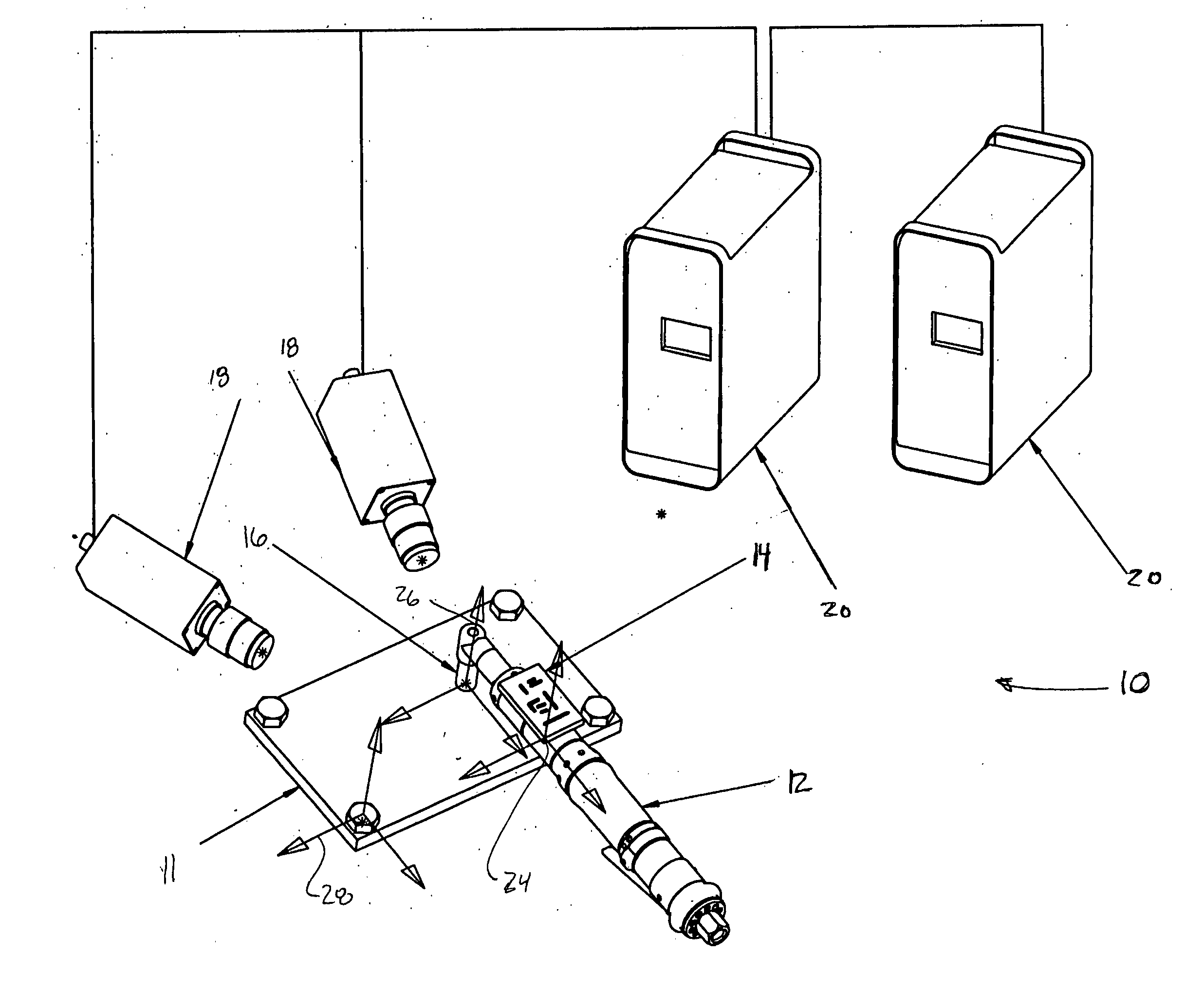
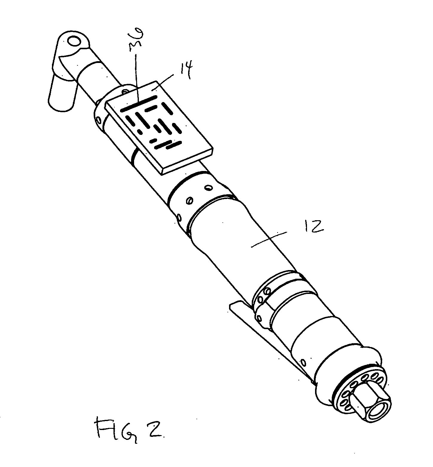
[0011]The invention is an integrated system for tracking and identifying the position and orientation of an object using a target that may be uniquely identifiable based upon an image obtained by a video imaging source and subsequent analysis within the mathematical model in the system software. It scales from a single video imaging source to any number of video imaging sources, and supports tracking any number of targets simultaneously. It uses off-the-shelf hardware and standard protocols (wire or wireless). It supports sub-millimeter-range accuracies and a lightweight target, making it appropriate for a wide variety of tracking solutions.

Problems solved by technology

A number of systems have been proposed which attempt to track such events but each system has some specific limitations which make if difficult to use in many manufacturing facilities.
However, the system does not monitor which particular nut is being acted upon.
However, ultrasound tracking does not work in the presence of loud ambient noise.
In particular, the high frequency metal-on-metal noise that is abundant in a heavy manufacturing environment would be problematic for such a system.
In such an environment accuracy degrades to the point of uselessness.
As well, these systems are relatively expensive.
It's a simple, accurate technique for measuring position, but it is ergonomically untenable for most workspace situations.
From an ergonomic and safety perspective, such a system would not be feasible.

Method used


Image

  • Vision-based position tracking system
  • Vision-based position tracking system
  • Vision-based position tracking system

Examples


Embodiment Construction

[0022]The present invention will now be described more fully hereinafter with reference to the accompanying drawings, in which preferred embodiments of the invention are shown. This invention may, however, be embodied in many different forms and should not be construed as limited to the embodiments set forth herein; rather, these embodiments are provided so that this disclosure will be thorough and complete, and will fully convey the scope of the invention to those skilled in the art. Like numbers refer to like elements throughout.

[0023]As will be appreciated by one of skill in the art, the present invention may be embodied as a method, data processing system or program product. Furthermore, the present invention may include a computer program product on a computer-readable storage medium having computer-readable program code means embodied in the medium. Any suitable computer readable medium may be utilized including hard disks, CD-ROMs, optical storage devices, or magnetic storage...


PUM


Abstract

The invention is directed to a tracking system for tracking the use of an object on a work piece within a predetermined work space comprising a target, at least one video imaging source and a computer. The target is attached to the object and calibrated to derive an “Object Tracking Point”. Each target has a predetermined address space and a predetermined anchor. At least one video imaging source is arranged such that the work piece is within the field of view. Each video imaging source is adapted to record images within its field of view. The computer is for receiving the images from each video imaging source and comparing the images with the predetermined anchor and the predetermined address, calculating the location of the target and the tool attached thereto in the work space relative to the work piece.

Description

CROSS REFERENCE TO RELATED PATENT APPLICATION[0001]This patent application relates to U.S. Provisional Patent Application Ser. No. 60 / 773,686 filed on Feb. 16, 2006 entitled A VISION-BASED POSITION TRACKING SYSTEM which is incorporated herein by reference in its entirety.FIELD OF THE INVENTION[0002]The present invention is related generally to a method for visually tracking an object in three dimensions with six degrees of freedom and in particular to a method of calculating the position and orientation of a target attached to an object and further calculating the position and orientation of the object's tracking point.BACKGROUND OF INVENTION[0003]There is a need in manufacturing to be able to record specific predetermined events relating to sequence and location of operations in a work cell. For example the recording of the precise location and occurrence of a series of nutrunner tightening events during a fastening procedure would contribute to the overall quality control of the m...

Claims


Application Information

Patent Timeline
IPC IPC(8): H04N7/18
CPCG01S5/163
Inventor ATKINSON, KEVINDIMITROV, NIKOLARAWLINGS, ROSS
Owner RADIX CO LTD
Learn More