Magnetoresistive head and magnetic storage apparatus

a magnetic storage and head technology, applied in the direction of magnetic recording heads, data recording, instruments, etc., can solve the problems of deterioration in the function of shields as electrodes, heat dissipation properties, and susceptibility to read instability, and achieve low area-resistance products and high mr ratios

Inactive Publication Date: 2007-08-16
WESTERN DIGITAL TECH INC
View PDF9 Cites 7 Cited by
  • Summary
  • Abstract
  • Description
  • Claims
  • Application Information

AI Technical Summary

Benefits of technology

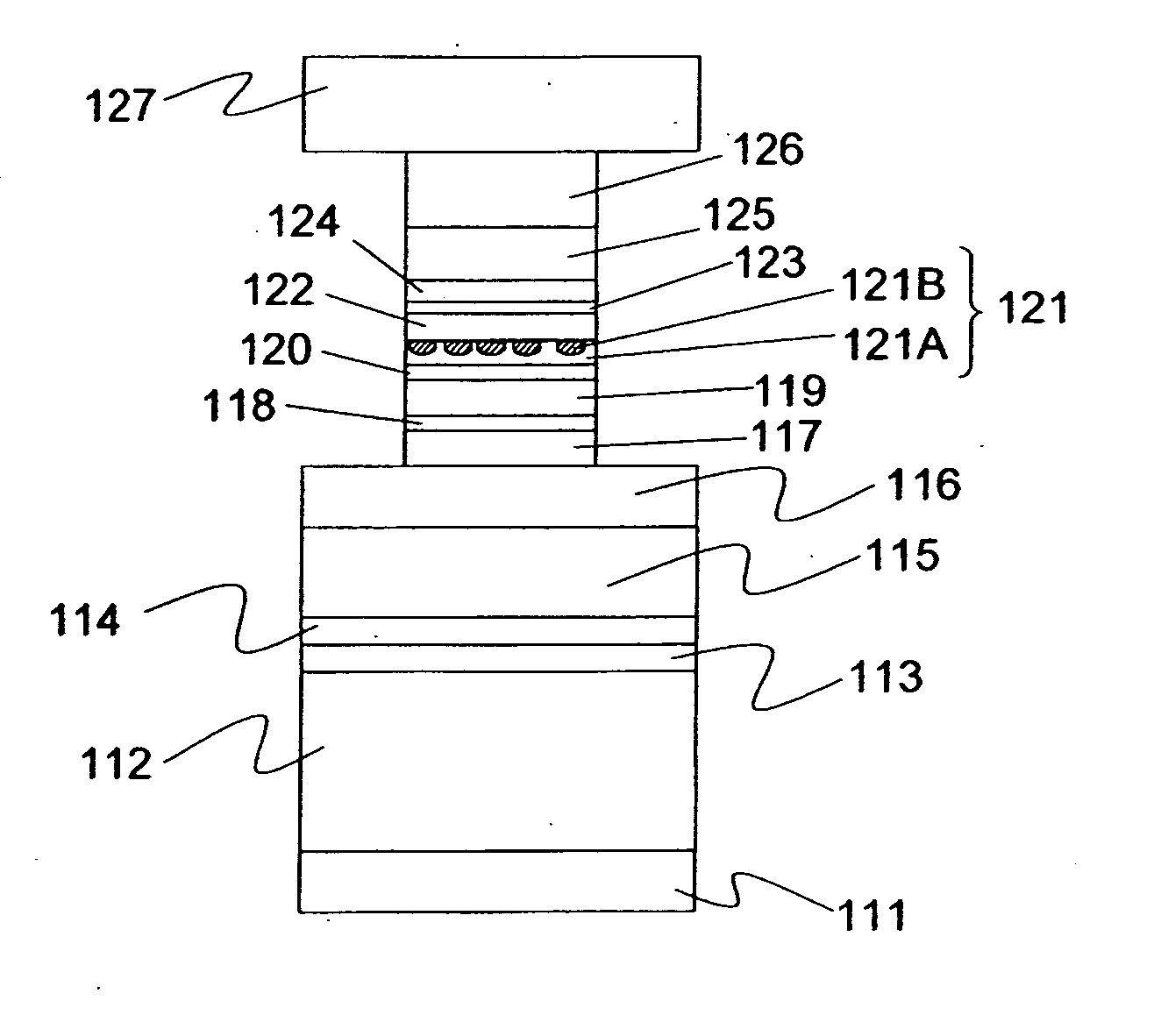
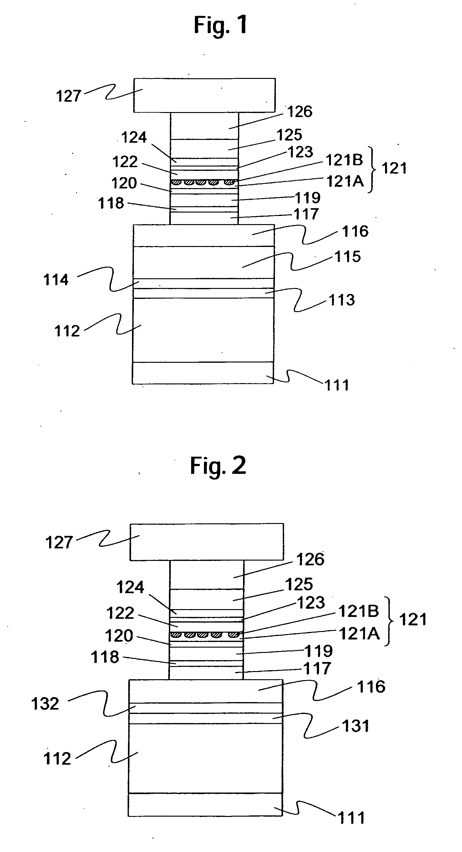
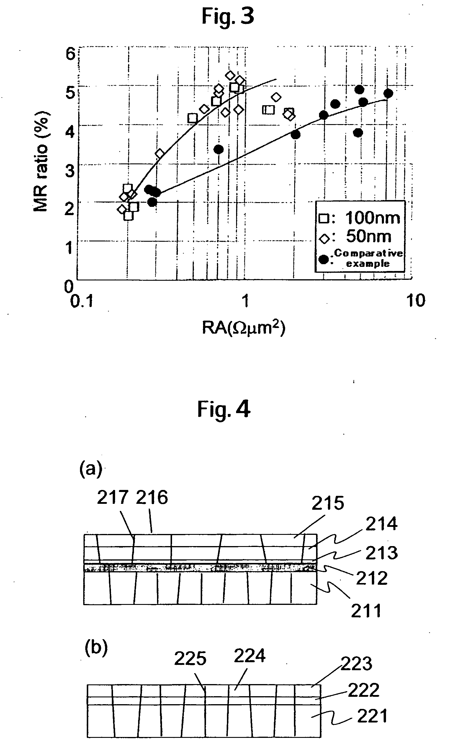
[0009] Embodiments in accordance with the present invention provide a Current Perpendicular to the Plane-Giant Magnetoresistive (CPP-GMR) head exhibiting a high MR ratio with a low area-resistance product. Referring to the specific embodiment of FIG. 1, a lower shield is made up of a first shield layer 112 / a crystalline reset layer / a second shield layer 115, and an amorphous material is used in at least a part of the crystalline reset layer, thereby controlling crystallinity of the second lower shield / the CPP-GMR head.

Problems solved by technology

Further, in the case of using the Co base amorphous alloy for the shields, there exist problems such as deterioration in the function of the shields as the electrodes, owing to high resistance of the Co base amorphous alloy, deterioration in heat dissipation properties, and susceptibility to occurrence of read instability attributable to the shields.
A problem with a conventional CPP-GMR head lies in that even if the GMR film is formed on a NiFe shield normally as thick as not less than 1 μm, stable and excellent properties cannot be obtained.
If the area-resistance product is high, read head performance at high frequency deteriorates as enhancement in recording density advances, and the GMR film as described is therefore not recommendable for application to the magnetic head.

Method used


Image

  • Magnetoresistive head and magnetic storage apparatus
  • Magnetoresistive head and magnetic storage apparatus
  • Magnetoresistive head and magnetic storage apparatus

Examples


embodiment 1

[0037] A read head (magnetoresistive head) to which embodiments in accordance with the present invention is applied, was manufactured. FIG. 5 is a view showing a magnetoresistive head according to the present embodiment, as seen from an air bearing surface. A process for manufacturing the same is substantially the same as the process for manufacturing the test chip according to the Embodiment 1. First, an NiFe film about 1.5 μm thick, as a first shield layer 411 that is a part of a lower shield, is formed by the pattern plating method on a nonmagnetic substrate obtained by forming an insulating layer composed of alumina followed by precision polishing. The surface of the NiFe film as the first shield layer is subjected to planarization by use of the CMP method. As the surface is oxidized, an oxidized film is first removed by the ion milling method. The first shield layer 411, as it is, is transferred to a deposition chamber communicating therewith in a vacuum so as to prevent the fi...

embodiment 4

[0050] A hard disk drive using the magnetic head composed of perpendicular magnetic recording head and reproducing head, fabricated according to an Embodiment 4, was manufactured. FIG. 10 is a schematic illustration of the hard disk drive, in which FIG. 10A is a plan schematic diagram, and FIG. 10B is a sectional schematic diagram taken on line A-A′ in FIG. 10A.

[0051] For a magnetic disk 811, use was made of a granular medium for perpendicular recording, composed of CoCrPt, and SiO2. For a magnetic head 813, use was made of the magnetic head as described with reference to Embodiment 4. The magnetic disk 811 for magnetically recording information is rotated by a spindle motor 812, and the magnetic head 813 is guided onto a track of the magnetic disk 811 by an actuator 814. That is, with the hard disk drive, the reproducing head, and the recording head, formed on the magnetic head 813, come in close proximity to a predetermined position on the magnetic disk 811 by this mechanism so as...


PUM

PropertyMeasurementUnit
thicknessaaaaaaaaaa
thickaaaaaaaaaa
thickaaaaaaaaaa

Abstract

Embodiments in accordance with the present invention provide a Current Perpendicular to the Plane-Giant Magnetoresistive (CPP-GMR) head exhibiting a high magnetoresistance (MR) ratio with a low area-resistance product. A lower shield is made up of a first shield layer/a crystalline reset layer/a second shield layer, and an amorphous material is used in at least a part of the crystalline reset layer, thereby controlling crystallinity of the second lower shield/the CPP-GMR head.

Description

CROSS-REFERENCE TO RELATED APPLICATION [0001] The instant nonprovisional patent application claims priority to Japanese Patent Application No. 2006-011579, filed Jan. 19, 2006 and incorporated by reference for all purposes herein. BACKGROUND OF THE INVENTION [0002] Embodiments in accordance with the present invention relate to a magnetic head and a magnetic storage apparatus, capable of coping with a high areal recording density. [0003] A giant magnetoresistive (GMR) film called a spin-valve has been in use as material for a read head of a HHD (Hard Disk Drive), as progress toward higher magnetic recording densities advances, enabling a read output to be enhanced up to now due to improvement on film makeup. A film makeup of the spin-valve has a structure comprising an antiferromagnetic layer / a pinned ferromagnetic layer / a non-magnetic intermediate layer / a free ferromagnetic layer. As magnetization of the pinned ferromagnetic layer is pinned by an interlayer coupling field occurring ...

Claims


Application Information

Patent Timeline
Patent Type & Authority Applications(United States)
IPC IPC(8): G11B5/127
CPCG11B5/3912
Inventor HOSHINO, KATSUMIHOSHIYA, HIROYUKIOKADA, YASUYUKI
Owner WESTERN DIGITAL TECH INC
Why Eureka
Try Eureka