

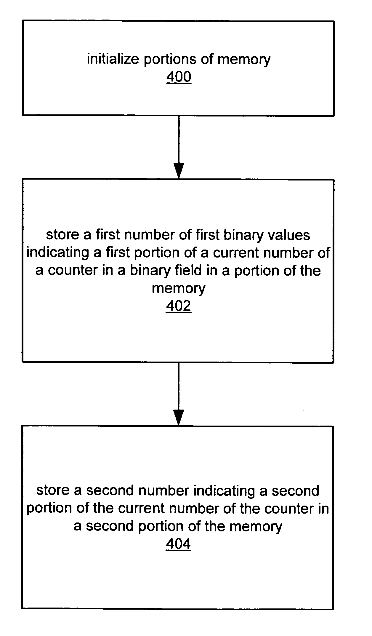
Method for implementing a counter in a memory with increased memory efficiency
a technology of counters and memory, applied in the field of counters, can solve problems such as wear on flash cells, and achieve the effect of increasing memory life and reducing the number of operations
- Summary
- Abstract
- Description
- Claims
- Application Information
AI Technical Summary
Benefits of technology
Problems solved by technology
Method used
Image

Examples
Embodiment Construction
FIG. 1—Computer System
[0024]FIG. 1 illustrates a computer system 82 suitable for implementing some embodiments of the present invention. However, it should be noted that various other systems are envisioned, including devices (e.g., handheld devices, e.g., digital music players, digital cameras, etc.), embedded systems (e.g., systems on chips (SoCs), cellular telephones, copiers, calculators, engine controllers, measurement analyzers, programmable logic controllers, videogame consoles, etc.), and other suitable systems. Some embodiments of a method for implementing and executing a counter or other memory intensive function in memory are described below.
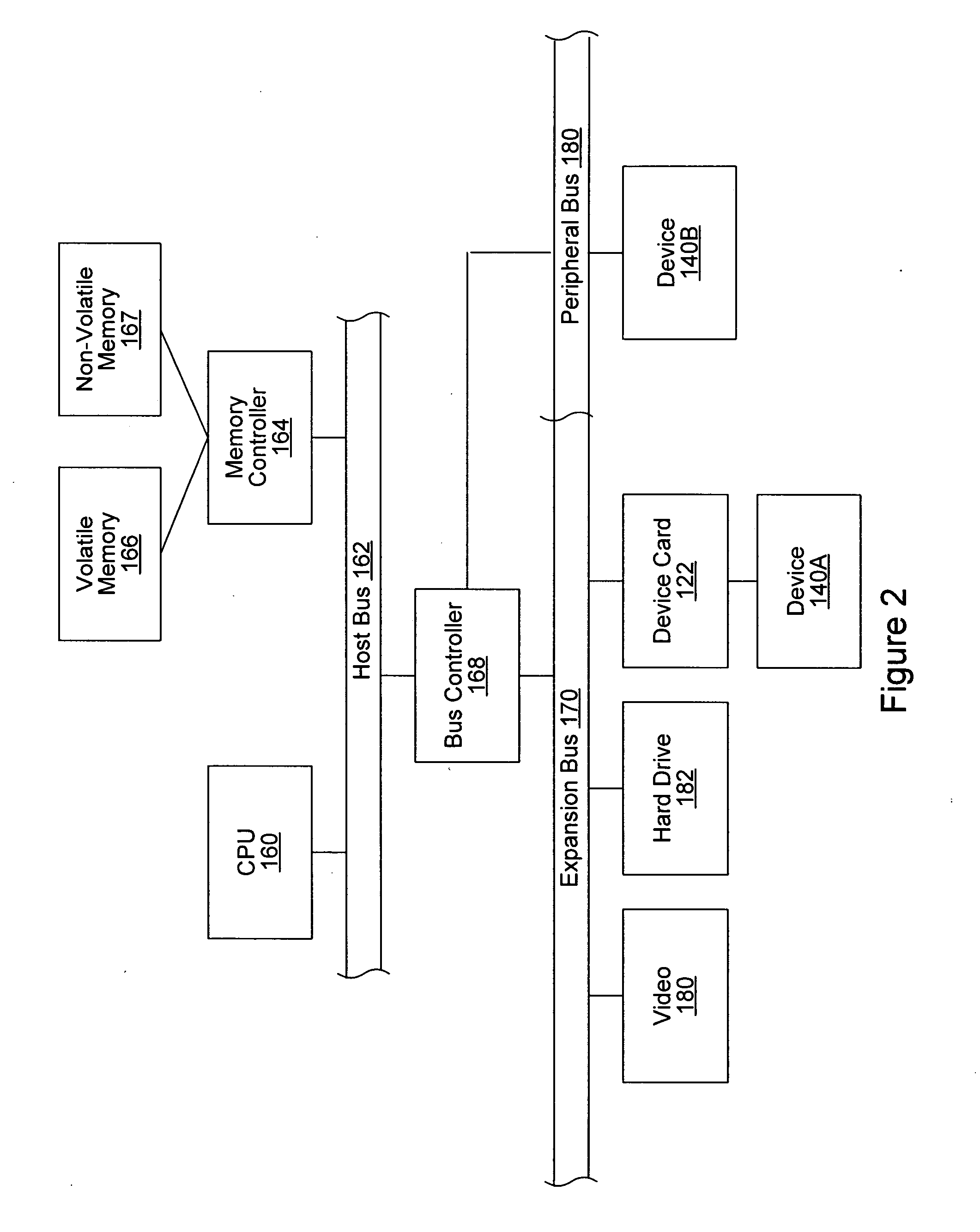
[0025] The computer system 82 may include a memory medium(s) on which one or more computer programs or software components according to one embodiment of the present invention may be stored. The memory medium may also store operating system software, as well as other software for operation of the computer system.
[0026] The computer ...
PUM
 Abstract
Description
Claims
Application Information