Handover control apparatus, base station, edge router, relay router, radio terminal unit, mobile communication system, and handover control method

a control apparatus and handover technology, applied in the field of handover control apparatus, can solve problems such as waste of network resources, and achieve the effects of preventing packet miss-ordering, effective utilization of network resources, and reducing the number of handovers

Inactive Publication Date: 2007-08-16
NTT DOCOMO INC
View PDF4 Cites 17 Cited by
  • Summary
  • Abstract
  • Description
  • Claims
  • Application Information

AI Technical Summary

Benefits of technology

[0011] The present invention has been accomplished in view of the above problems and an object of the invention is to provide a handover control apparatus, a base station, an edge router, a relay router, a radio terminal unit, a mobile communication system, and a handover control method capable of implementing forwarding packet data through an optimal path to the radio terminal unit after movement in handover control and thereby achieving effective utilization of network resources and prevention of the packet miss-ordering during the handover.
[0015] In this configuration, the appropriate relay router is instructed to buffer the data from the correspondent node, whereby it is feasible to buffer the data to be transmitted to the radio terminal unit under the handover, and thereby prevent data reception loss.
[0023] In this configuration, the data from the correspondent node is buffered in the relay router, whereby it is feasible to nullify the redundant path in forwarding packet data and thereby achieve the effective utilization of network resources and the prevention of packet miss-ordering during the handover. In the conventional technology, since during the handover the data was buffered in the previous edge router having been connected to the radio terminal unit, the data was forwarded from the edge router connected before the movement, through the redundant path via a plurality of routers to the radio terminal unit after the movement, which resulted in waste of network resources. In addition, there simultaneously existed two paths: the path for forwarding buffered packet data from the previous edge router to the new edge router after movement and the path for forwarding packet data from the correspondent node to the edge router after movement; therefore, there occurred the packet miss-ordering because of delivery of the packets in a mixed state.
[0025] In this configuration, the data from the correspondent node is buffered in the relay router, whereby it is feasible to nullify the redundant path in forwarding packet data and thereby achieve the effective utilization of network resources and the prevention of packet miss-ordering during the handover. In the conventional technology, since during the handover the data was buffered in the previous edge router having been connected to the radio terminal unit, the data was forwarded from the edge router connected before the movement, through the redundant path via a plurality of routers to the radio terminal unit after the movement, which resulted in waste of network resources. In addition, there simultaneously existed two paths: the path for forwarding buffered packet data from the previous edge router to the new edge router after movement and the path for forwarding packet data from the correspondent node to the edge router after movement; therefore, there occurred the packet miss-ordering because of delivery of the packets in a mixed state.

Problems solved by technology

Namely, the packet data is forwarded through the redundant path during the handover control and this poses the problem of waste of network resources.

Method used


Image

  • Handover control apparatus, base station, edge router, relay router, radio terminal unit, mobile communication system, and handover control method
  • Handover control apparatus, base station, edge router, relay router, radio terminal unit, mobile communication system, and handover control method
  • Handover control apparatus, base station, edge router, relay router, radio terminal unit, mobile communication system, and handover control method

Examples


Embodiment Construction

Embodiments of the Invention

[0032] An embodiment of the present invention will be described below in detail with reference to the drawings.

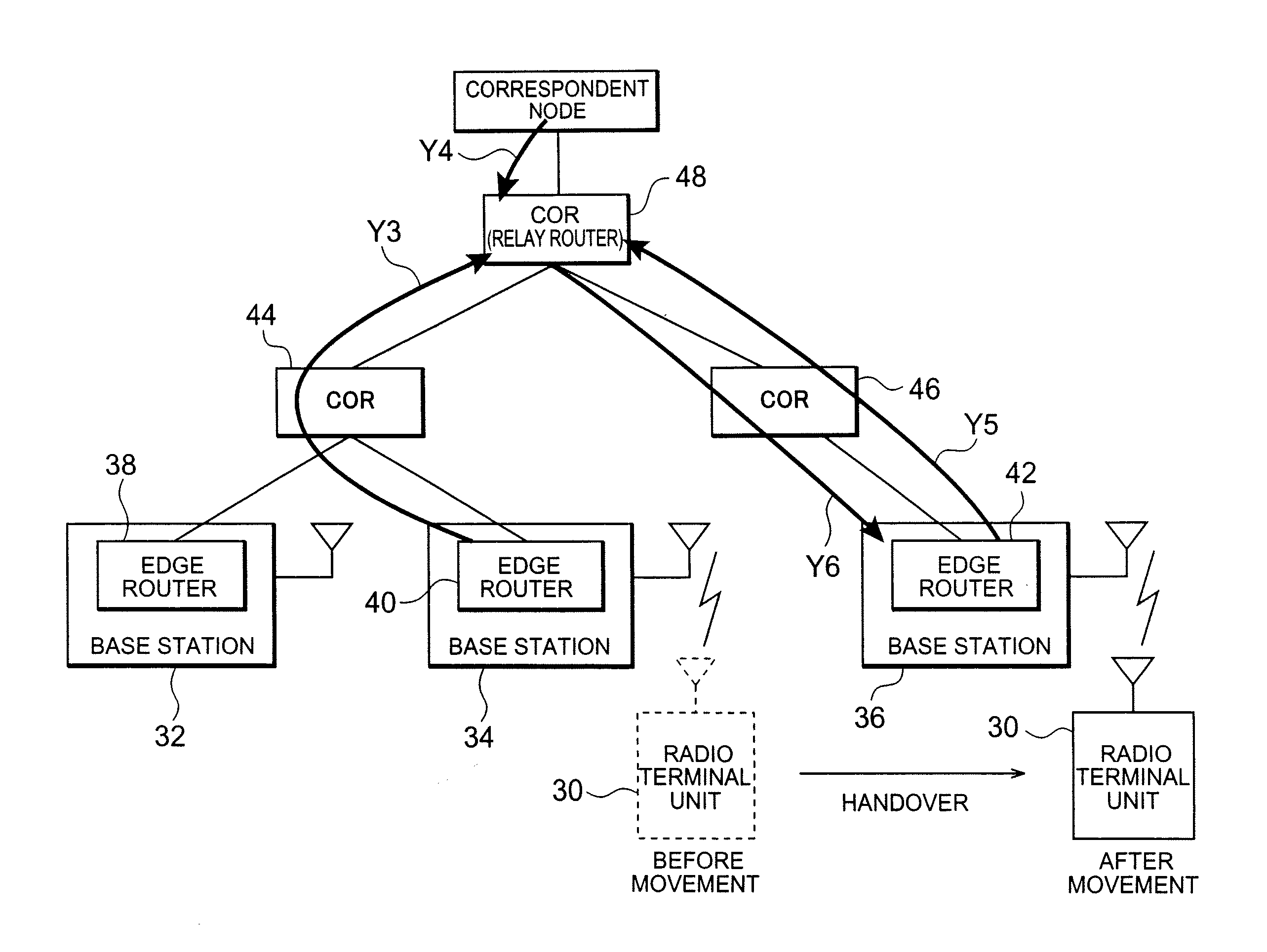
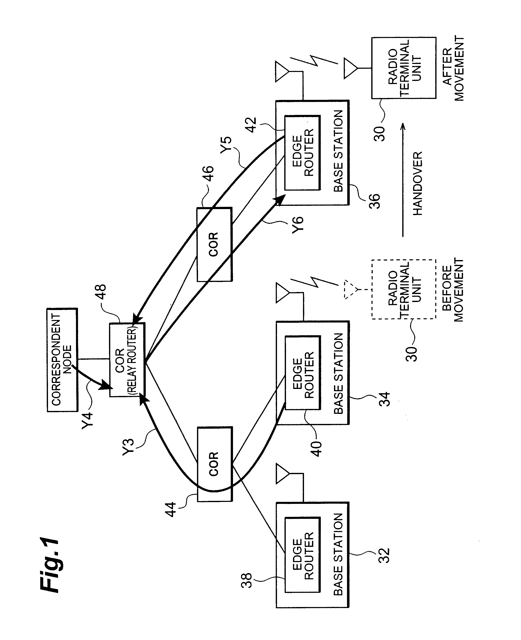
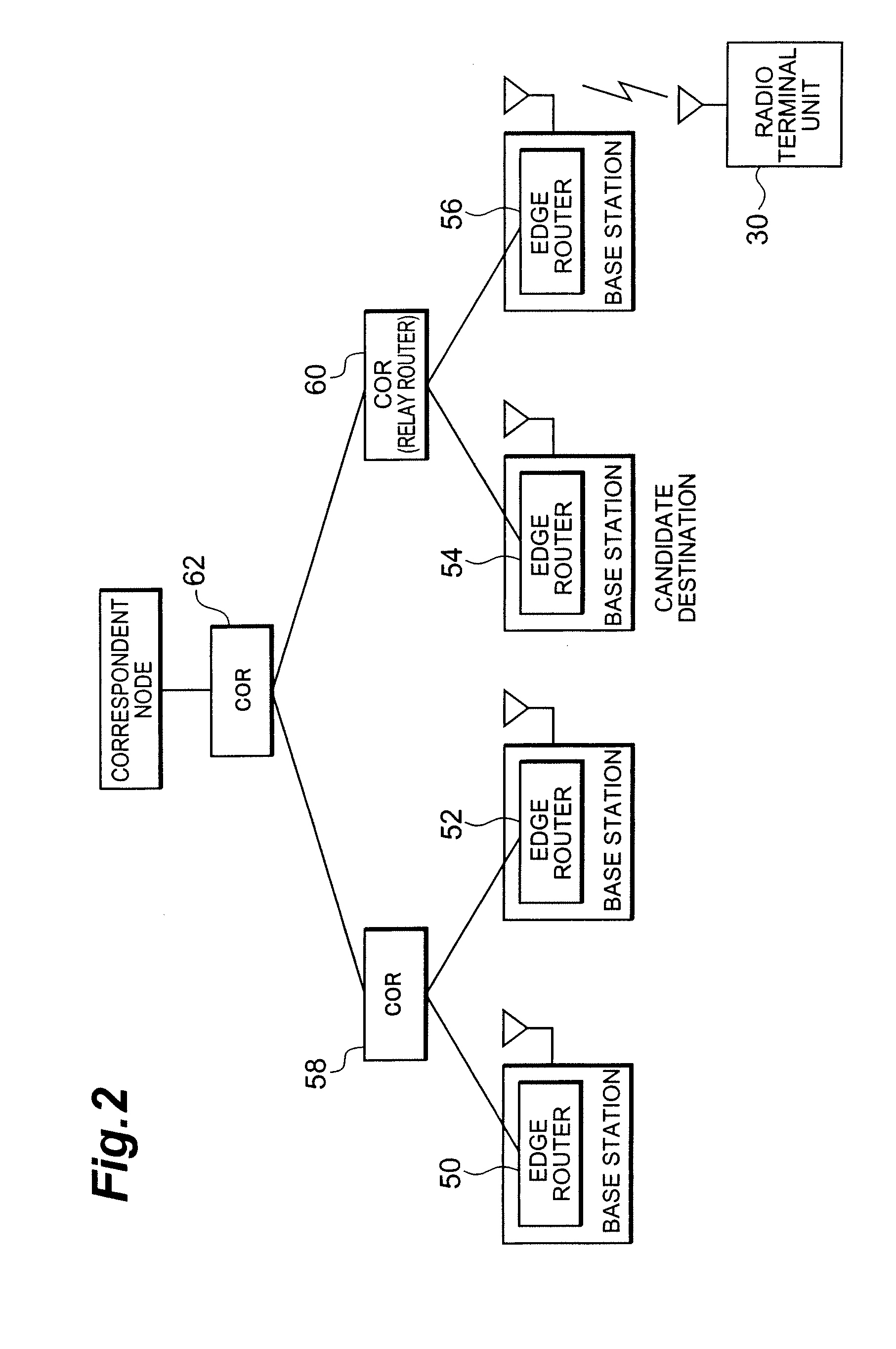
[0033]FIG. 1 is a block diagram showing a configuration of a mobile communication system according to an embodiment of the present invention.

[0034] This mobile communication system shown in FIG. 1 is comprised of a radio terminal unit 30 which is a mobile communication means such as a cellular phone or the like, a plurality of base stations 32, 34, 36 for radio communication with the radio terminal unit 30, edge routers 38, 40, 42 provided in the respective base stations 32-36, and CORs 44, 46, 48 connected to these edge routers 38-42.

[0035] Here the CORs 44-48 are arranged in a hierarchical structure with COR 48 at the top, in which the edge routers 38, 40 are under COR 44, the edge router 42 under COR 46, and the edge routers 38-42 under COR 48 through the CORs 44, 46. The edge routers 38, 40, 42 retain information about adjacent edge route...


PUM


Abstract

When a radio terminal unit 30 undergoes a handover between base stations 34, 36, a previous edge router 40 having been connected to the radio terminal unit 30, out of edge routers 40, 42 provided in respective base stations 34, 36, provides an instruction to instruct a relay router 48, under which the edge router 40 and every edge router 42 in the base station 36 as a candidate for a destination of the movement are connected, to buffer data from a correspondent node, and instructs the relay router to forward the data buffered in the relay router 48 according to the instruction, to the radio terminal unit 30 after the movement, after completion of the handover, whereby the buffered data is forwarded to the radio terminal unit 30. This implements forwarding packet data through the optimal path to the radio terminal unit after the movement in the handover control and achieves effective utilization of network resources and reduction of handover transactions.

Description

CROSS-REFERENCE TO RELATED APPLICATIONS [0001] This application is a Continuation of U.S. patent application Ser. No. 10 / 399,785 filed Apr. 28, 2003, which was a National Stage Application of PCT Application No. PCT / JP02 / 08581 filed Aug. 26, 2002, and claims priority to Japanese Patent Application No. P2001-256760, filed Aug. 27, 2001. The contents of U.S. application Ser. No. 10 / 399,785 are incorporated herein by reference in their entirety.TECHNICAL FIELD [0002] The present invention relates to a handover control apparatus, a base station, an edge router, a relay router, a radio terminal unit, a mobile communication system, and a handover control method. BACKGROUND ART [0003] The conventional schemes proposed in IETF (Internet Engineering Task Force) (for example, Govind Krishnamurthi, Robert C. Chalmers, Charles E. Parkins, “Buffer management for smooth handovers in ipv6.,” INTERNET DRAFT, March 2001) involve handover control to buffer packet data. [0004] In this handover control...

Claims


Application Information

Patent Timeline
Patent Type & Authority Applications(United States)
IPC IPC(8): H04Q7/00H04L12/701H04W28/00H04W36/00H04W36/12H04W36/18H04W40/34
CPCH04L45/00H04W36/18H04W36/12
Inventor ISOBE, SHINICHIIGARASHI, KENIWASAKI, ATSUSHI
Owner NTT DOCOMO INC
Why Eureka
Try Eureka