Wireless communication device and wireless communication method

a wireless communication and wireless communication technology, applied in the field of wireless communication devices and wireless communication methods, can solve the problems of insufficient reduction of communication errors by automatic gain control alone, inability to reduce the effect of discharge lamp fading using only automatic gain control, and inability to reduce so as to prevent a drop in communication quality and avoid data errors. , the effect of reducing the number of times data must be retransmitted

Inactive Publication Date: 2007-08-16
PANASONIC CORP
View PDF14 Cites 23 Cited by
  • Summary
  • Abstract
  • Description
  • Claims
  • Application Information

AI Technical Summary

Benefits of technology

[0014] The present invention thus makes it possible to avoid data errors in the reception-side wireless terminal, and makes it possible to prevent a drop in communication quality. The number of times data must be retransmitted can therefore be reduced, and stable throughput can be achieved.

Problems solved by technology

Communication errors cannot be sufficiently reduced by automatic gain control alone, however, because both the amplitude and the phase of the received signal vary in a transmission path environment subject to discharge lamp fading.
In addition, the in-band frequency pass characteristics also change due to discharge lamp fading in the transmission of OFDM signals and other broadband signals.
Reducing the effect of discharge lamp fading using only automatic gain control is thus difficult.

Method used


Image

  • Wireless communication device and wireless communication method
  • Wireless communication device and wireless communication method
  • Wireless communication device and wireless communication method

Examples


embodiment 1

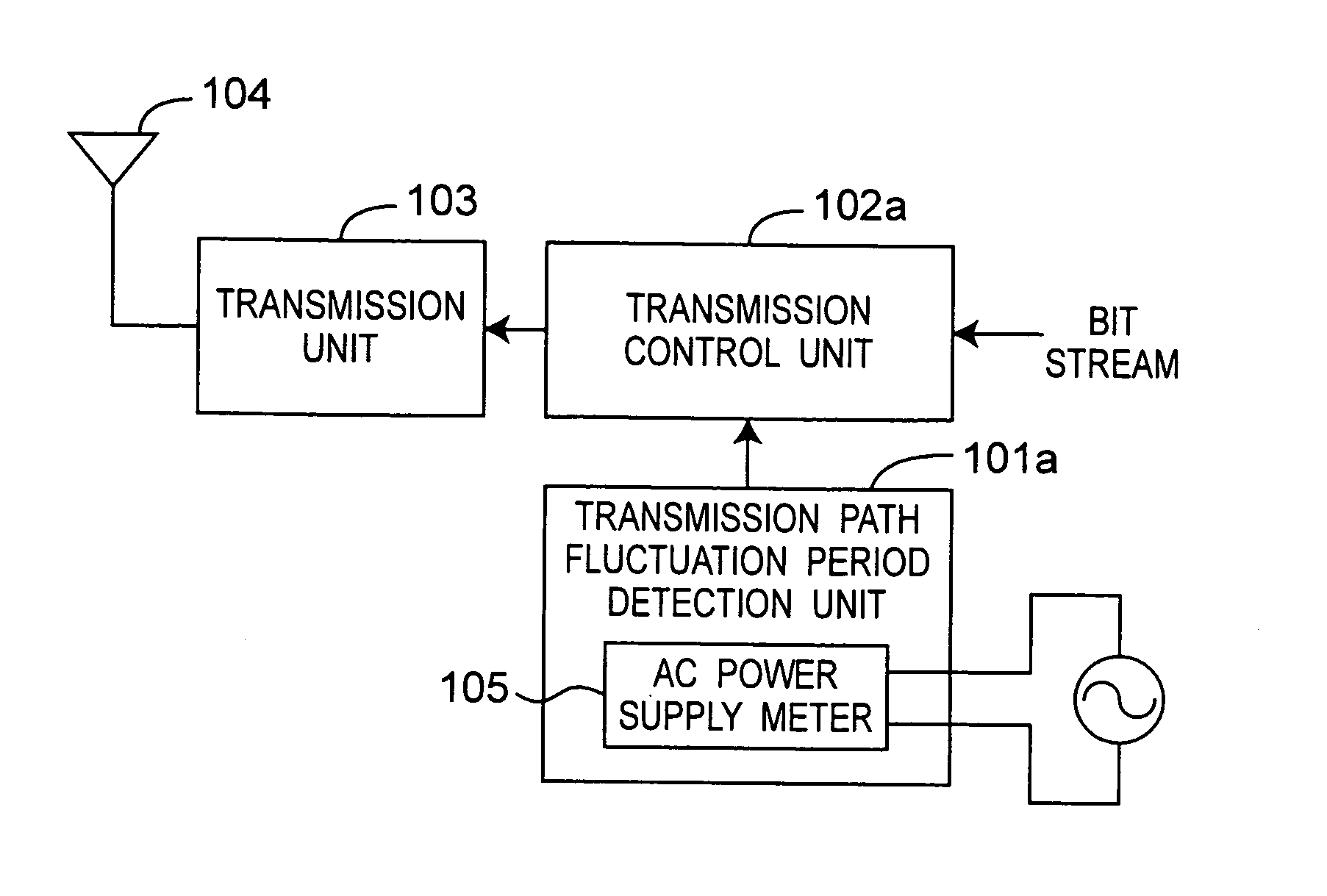
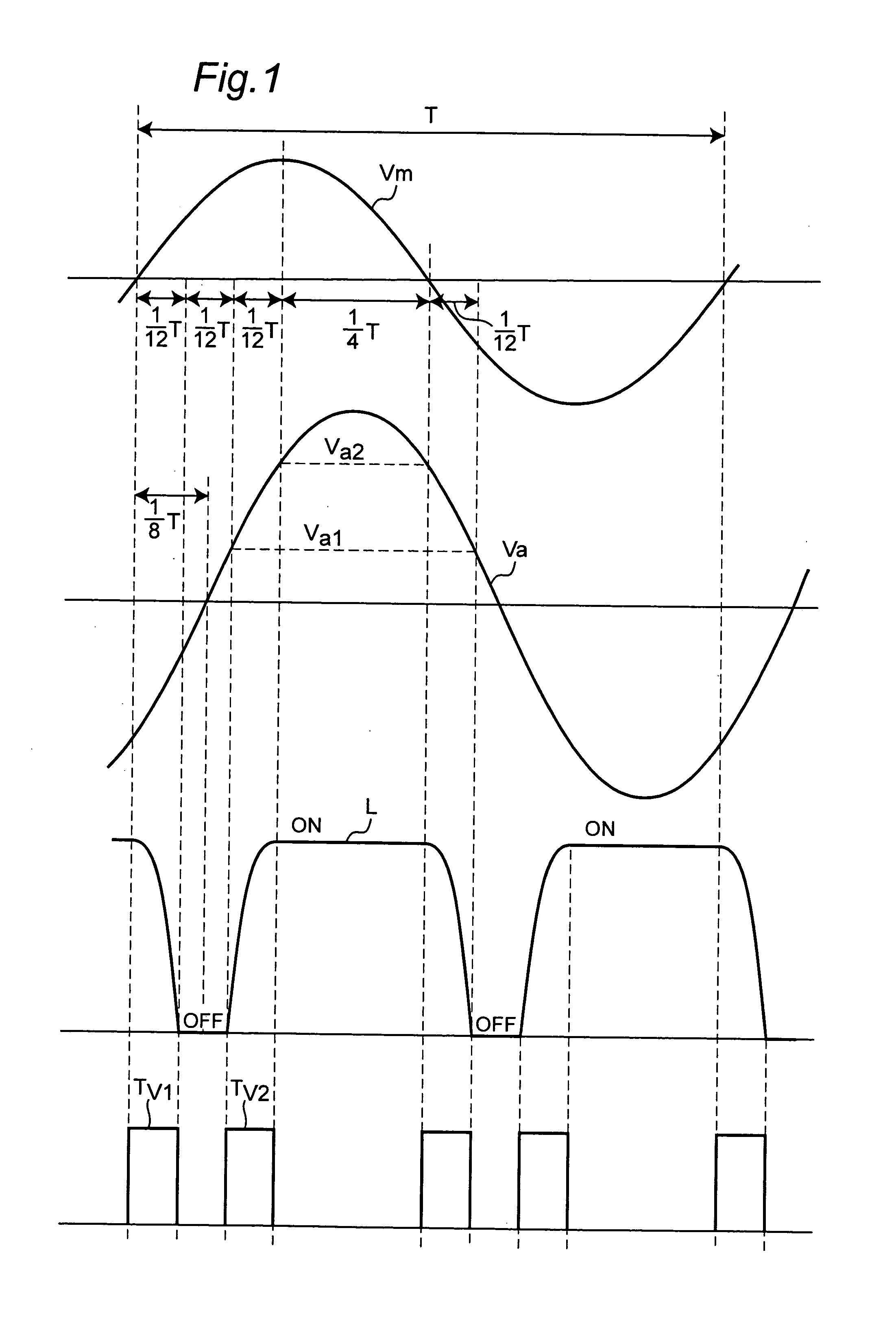
[0095]FIG. 2A is a block diagram of a wireless communication apparatus according to a first embodiment of the invention. In this embodiment of the invention the transmission path fluctuation period is period Tv1 from the zero cross of the AC power source to ( 1 / 12)T, and period Tv2 from (⅙)T to ( 1 / 12)T.

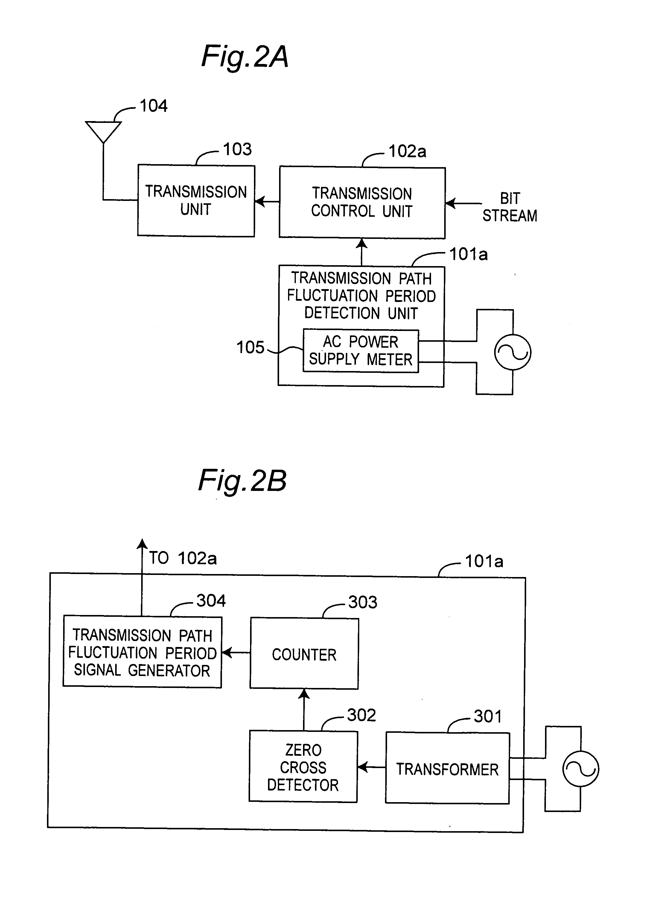
[0096] As shown in FIG. 2A, the wireless communication apparatus has a transmission path fluctuation period detection unit 101a, transmission control unit 102a, transmission unit 103, and antenna 104. The transmission path fluctuation period detection unit 101a has an AC power supply meter 105 and is connected to an external AC power source. The transmission path fluctuation period detection unit 101a outputs a fluctuation period signal indicating the transmission path fluctuation periods Tv1 and Tv2 as shown in FIG. 2D. The transmission control unit 102a receives the transmitted bit stream data and the fluctuation period signal, modulates the bit stream using QAM coding, for exampl...

embodiment 2

[0106]FIG. 4A is a block diagram showing the arrangement of a wireless communication apparatus according to a second embodiment of the invention.

[0107] As shown in FIG. 4A, a wireless communication apparatus according to this embodiment of the invention has a transmission path fluctuation period detection unit 101b, a transmission control unit 102a to which the transmission path fluctuation period signals Tv1 and Tv2 output by transmission path fluctuation period detection unit 101b are input, a transmission unit 103 to which the transmission signal output by transmission control unit 102a is input, and a antenna 104 connected to the transmission unit 103. A photoelectric conversion unit 106 is rendered inside the transmission path fluctuation period detection unit 101b.

[0108]FIG. 5 is a waveform diagram with time on the horizontal axis describing the operation of the wireless communication apparatus according to this second embodiment of the invention.

[0109] Like elements and wa...

embodiment 3

[0116]FIG. 6A is a block diagram showing the arrangement of a wireless communication apparatus according to a third embodiment of the invention.

[0117] As shown in FIG. 6A, a wireless communication apparatus according to this embodiment of the invention has a transmission path fluctuation period detection unit 101c, a transmission control unit 102a to which the transmission path fluctuation period signals Tv1 and Tv2 output by transmission path fluctuation period detection unit 101c are input, a transmission unit 103 to which the transmission signal output by transmission control unit 102a is input, a transmission / reception switch 107 which is connected to the transmission unit 103 and switches the input / output signals during transmission and reception, a antenna 104 connected to the transmission / reception switch 107, and a reception unit 108 which is connected to the transmission / reception switch and based on the received wireless signal outputs reception data error information or ...


PUM


Abstract

When a wireless communication apparatus is used indoors where discharge lamps are used, flickering of the discharge lamp can cause transmission path fluctuations in which the amplitude or phase of the reception signal changes suddenly. The effect of this discharge lamp fading is that communication data errors occur easily and communication quality drops. A wireless communication apparatus according to the present invention has a transmission path fluctuation period detection unit (101) that detects the period in which transmission path fluctuation caused by discharge lamp increases, a transmission control unit (102) that sets transmission signal conditions based on the detected transmission path fluctuation period, a transmission unit (103) that generates and outputs the transmission signal based on these conditions, and an antenna (104) for transmitting the transmission signals. The wireless communication apparatus thus comprised stops wireless signal transmission during the transmission path fluctuation period or transmits a wireless signal that is resistant to data errors caused by change in the transmission path environment.

Description

BACKGROUND OF THE INVENTION [0001] The present invention relates to a wireless LAN or other wireless communication device or apparatus, and to a wireless communication method for the same. [0002] Local area networks (LAN) are increasingly common both in business and in the home, including wireless LANs that do not require wiring and allow free movement of the data terminals connected to the LAN. [0003] In a typical wireless LAN such as used today a wireless LAN control device (referred to as a “wireless access point” below) is connected by wire to a data socket, and a plurality of wireless LAN terminals communicate wirelessly with this wireless access point. [0004] Sudden changes in the wireless communication environment caused by fluorescent lights and other discharge lamps in wireless communication systems that are used indoors can easily generate communication data errors, thus degrading communication quality. [0005] A discharge lamp reflects radio frequency waves in the wireless...

Claims


Application Information

Patent Timeline
Patent Type & Authority Applications(United States)
IPC IPC(8): H04Q7/24H04B1/04H04B1/16H04J99/00
CPCH04B10/1149H04B1/0475
Inventor HOSOKAWA, SHUYATANAKA, KOICHIRO
Owner PANASONIC CORP
Why Eureka
Try Eureka