
Flowable bone grafts

Inactive Publication Date: 2007-08-16
DEPUY SPINE INC (US) +1
View PDF96 Cites 52 Cited by
  • Summary
  • Abstract
  • Description
  • Claims
  • Application Information

AI Technical Summary

Problems solved by technology

The regenerating potential of human bone appears to be limited.
Problems associated with autogeneic bone grafting include a limited source of donor bone and the need for an additional surgery to procure the tissue, which engenders the risk of high morbidity at the donor site.
For allogeneic bone grafts, potential risks include the transfer of diseases, immunological reactions from the host, poor osteogenic capacity of the transplanted bone, and high cost associated with a bone banking system.
There is a risk that the host will reject the material or that the implant will fail to integrate with normal skeletal tissue.
Ceramic materials such as tricalcium phosphate, although biocompatible with the host and bone, appear to lack sufficient mechanical properties of bone for general utility when used as an implant and the bone does not consistently grow into and become incorporated within the implant.
While the art has disclosed the use of mineralized collagen fibers as noted above, it has not disclosed or suggested flowable bone graft compositions that may be administered in a flowable form to the body via a cannula of a medical device, e.g. a needle, in which case materials and compositions noted above would not be conducive for such use.

Method used


Image

  • Flowable bone grafts
  • Flowable bone grafts

Examples


example 1

Roto-Milled Healos

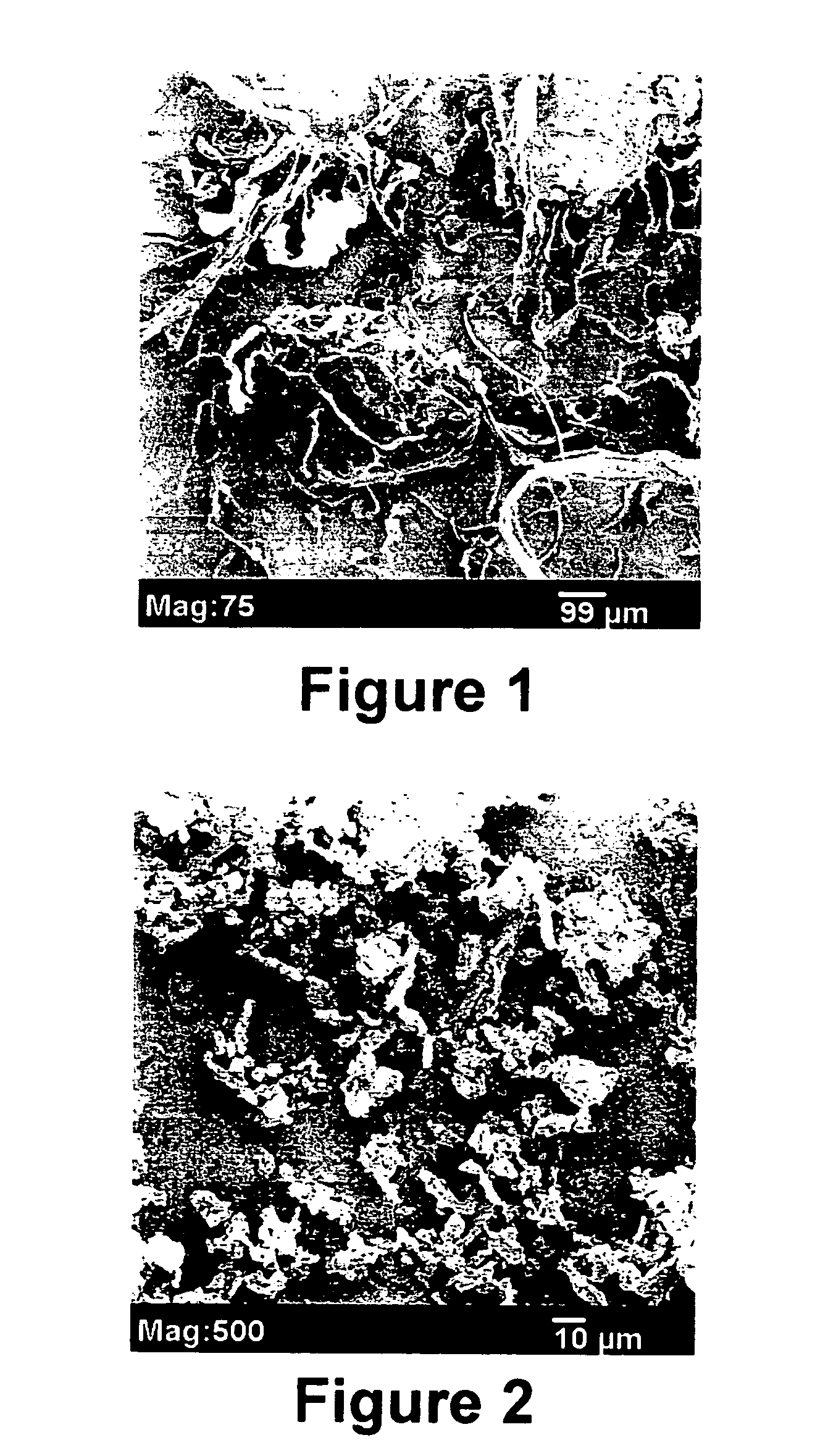
[0045] A porous, three-dimensional bone graft formed from mineralized collagen fibrils, sold under the tradename HEALOS (DePuy Spine, Inc., Mountain View, Calif.), was cut to smaller pieces of roughly 0.5 cm×2 cm and the pieces fed into a rotor-mill (Wiley Mini-Mill model 3383-L10, Thomas Scientific, Swedesboro, N.J.) fitted with a US Std. #20 mesh (Thomas Scientific, Swedesboro, N.J.). FIG. 1 shows a scanning electron micrograph of the roto-milled, irregularly shaped mineralized collagen particles comprising bound mineralized collagen fibrils.

example 2

Cryogenically-Milled Mineralized Collagen Fibrils

[0046] Mineralized collagen fibrils as described in Constantz were cut into smaller pieces and micronized with a 6800 Freezer Mill (SPEX CertiPrep, Metuchen, N.J.). The freeze / mill cycle consisted of a 20-minute initial cooling period followed by 10 cycles of 2 minutes milling and 2 minutes cooling between each milling cycle with an impact setting of 12. FIG. 2 shows a scanning electron micrograph of cryo-milled mineralized collagen fibrils.

example 3

Cryo-Milled Mineralized Collagen Fibrils Bound with Denatured Collagen

[0047] One gram of water-soluble collagen was added into 10 ml of deionized water. The solution was heated to 80° C. until the collagen was totally dissolved. The solution was cooled to and maintained at 40° C. The pH of the solution was adjusted to 7.4 using 1N NaOH. 150 milligrams of cryo-milled, mineralized collagen fibrils as show in FIG. 2 were suspended in 3 ml of the denatured collagen solution and vortexed. 3 ml of the slurry so formed was poured into 60 ml of olive oil maintained at 40° C. under stirring at 400 rpm to form agglomerates of fibrils coated with denatured collagen. Stirring was continued for 10 minutes. The solution was transferred into an ice bath and stirred for 15 minutes at 200 rpm. 400 ml of cold acetone was added into the solution while the solution still was in the ice bath. The solution was kept in the ice bath for 40 minutes. Coated agglomerates were collected by filtration. Coated ...


PUM

PropertyMeasurementUnit
Percent by massaaaaaaaaaa

Abstract

The present invention is directed to bone graft compositions suitable for administration to the body via a cannula, where the compositions contain mineralized collagen particles and a fluid biocompatible carrier having the mineralized collagen particles substantially uniformly distributed there through, which particles contain bound mineralized collagen fibrils substantially uniformly distributed there through and a binder for the fibrils; and to methods of making such particles.

Description

FIELD OF THE INVENTION [0001] The present invention relates to particles containing bound mineralized collagen fibrils and flowable bone graft compositions utilizing such particles. BACKGROUND OF THE INVENTION [0002] The regenerating potential of human bone appears to be limited. Bone graft has been employed for repairing discontinuity defects in bone that can result from traumatic injuries, congenital deformities, and tumor resection. Bone graft also has been used in bone contouring and augmentation, as well as in stimulating formation of bone at specific sites within the body, e.g. a spinal fusion. [0003] The clinical approach to repairing or restoring bone involves substituting the missing tissue with an autogeneic and allogeneic bone graft or processed bone. Problems associated with autogeneic bone grafting include a limited source of donor bone and the need for an additional surgery to procure the tissue, which engenders the risk of high morbidity at the donor site. For allogen...

Claims


Application Information

Patent Timeline
IPC IPC(8): A61K35/32A61K38/17A61K38/18A61K35/28
CPCA61K38/39A61L27/26A61L27/3608A61L27/365A61L27/46A61K35/28A61L27/50A61K38/00C08L89/06A61L2430/02A61L2400/06A61L27/3804
Inventor YANG, CHUNLINAU-YEUNG, JACKYCHUN, IKSOODAVIS, MARKLIU, LUNATHAN, ARUNASHENOY, VIVEKTIMMER, MARK
Owner DEPUY SPINE INC (US)
Learn More