Toner, and image forming method and apparatus and process cartridge using the toner

a technology of toner and image bearing, which is applied in the field of toner, can solve the problems of easy deterioration of the charging properties of the toner, the tendency of electrostatic adhesion of the toner particles and embedded in the charger and the image bearing member, and the contact of the charger with the charger

Inactive Publication Date: 2007-08-16
RICOH KK
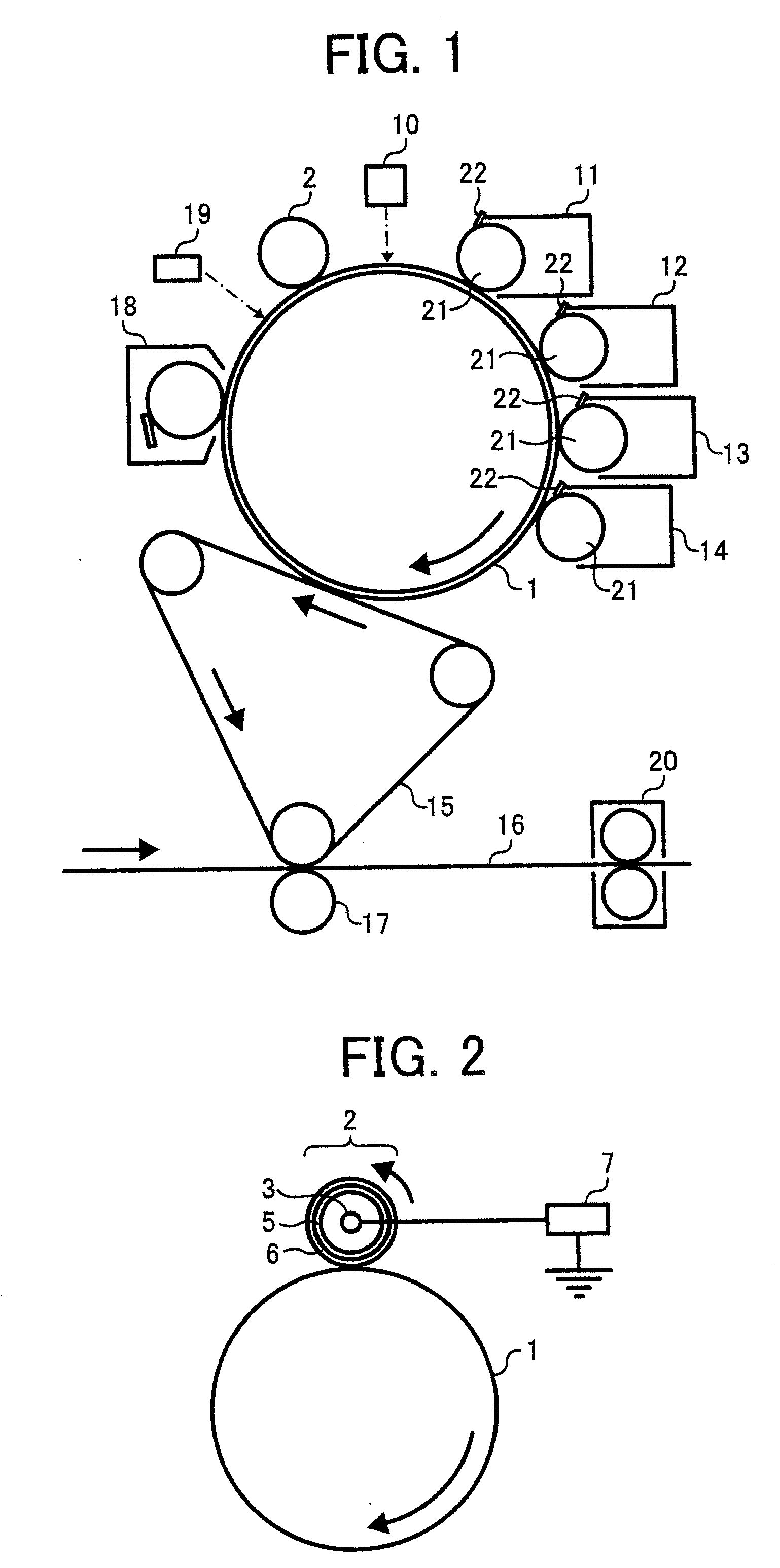
View PDF11 Cites 74 Cited by
  • Summary
  • Abstract
  • Description
  • Claims
  • Application Information

AI Technical Summary

Benefits of technology

[0025]As an aspect of the present invention, a toner is provided which includes toner particles including at least a binder resin, a colorant and a release agent, and an external additive including a first particulate inorganic material having a formula of MgxSiyOx+2y where each of x and y is an integer, and a number average secondary particle diameter of from 0.02 μm to 2 μm, wherein the first atomic ratio (Mg/Si) sin a surface portion of the first part

Problems solved by technology

Therefore, problems such that the residual toner particles are electrostatically adhered to and embedded into the charger and image bearing member tend to be caused.
Namely, contact chargers have a drawback in that the charging properties thereof easily deteriorate with time.
In general, it is impossible to impart a good combination of releasability and glossiness to toner, namely, the properties establish a trade-off relationship.
In general, toners including a large amount of wax therein tend to cause a problem in that the wax exudes from the surface of toner particles, and the free wax released from the toner particles deteriorates the image qualities.
Particularly, when the free wax is adhered to a developer bearing member or an image bearing member and forms a wax film thereon, various problems occur.
Specifically, a background development problem in that the background area of images is soiled with toner particles is caused.
In addition, when the wax film formed on an image bearing member is transferred to a charger, the charging ability of the charger deteriorates, and thereby a problem in that the image bearing member is defectively charged, resulting in deterioration of image qualities, is caused.
Further, since a granulation toner is manufactured (i.e., granulated) in an aqueous medium while using a surfactant, the resultant toner particles tend to have a relatively poor charge property compared with pulverization toners, and thereby problems such as the background development problem are easily caused.
In addition, when toner particles are prepared by a pulverization method, it is impossible to well disperse a relatively large amount of wax in the toner particles and therefore the particle diameter distribution of the wax particles (domains) in the toner particles is broad.
Therefore, the toner has an undesired composition.
As a result, the toner has a broad charge quantity distribution and thereby image quality problems due to defectively charged toner particles (such as the background development problem) are caused.
Further, when a wax is unevenly dispersed in toner particles, the toner particles tend to agglomerate.
As a result, the toner has poor transferability, resulting in formation of hollow images (such as hollow character or line

Method used


Image

  • Toner, and image forming method and apparatus and process cartridge using the toner
  • Toner, and image forming method and apparatus and process cartridge using the toner

Examples


preparation example 4

of Inorganic Material A

[0229]The procedure for preparation of the inorganic material A-2 was repeated except that the molar ratio MgO / SiO2 was changed to 1 / 1 and the concentrations of MgO and SiO2 in the 150-litter slurry were changed to 35.8 g / litter and 53.3 g / litter, respectively.

[0230]Thus, a particulate inorganic material A-4 was prepared.

[0231]As a result of X-ray diffraction analysis of the particulate inorganic material A-4, it was found that the material is made of a single phase of enstatite and has the following properties.

[0232]Average primary particle diameter: 0.09 μm

[0233]Specific surface area: 20.5 m2 / g

[0234]Average secondary particle diameter: 0.40 μm

[0235]Mg / Si atomic ratio in the entire toner: 1.01

[0236]Mg / Si atomic ratio in the surface portion of toner: 0.68

preparation example 5

of Inorganic Material A

[0237]The procedure for preparation of the inorganic material A-1 was repeated except that the calcination temperature was changed to 1200° C. Thus a particulate inorganic material A-5 was prepared.

[0238]As a result of X-ray diffraction analysis of the particulate inorganic material A-5, it was found that the material is made of a single phase of forsterite and has the following properties.

[0239]Average primary particle diameter: 0.15 μm

[0240]Specific surface area: 10.5 m2 / g

[0241]Average secondary particle diameter: 1.7 μm

[0242]Mg / Si atomic ratio in the entire toner: 2.05

[0243]Mg / Si atomic ratio in the surface portion of toner: 2.05

preparation example 6

of Inorganic Material A

[0244]The procedure for preparation of the inorganic material A-1 was repeated except that the molar ratio MgO / SiO2 was changed to 1 / 1 and the concentrations of MgO and SiO2 in the 150-litter slurry were changed to 35.8 g / litter and 53.3 g / litter, respectively.

[0245]Thus, a particulate inorganic material A-6 was prepared.

[0246]As a result of X-ray diffraction analysis of the particulate inorganic material A-6, it was found that the material is made of a single phase of enstatite and has the following properties.

[0247]Average primary particle diameter: 0.09 μm

[0248]Specific surface area: 20.5 m2 / g

[0249]Average secondary particle diameter: 0.40 μm

[0250]Mg / Si atomic ratio in the entire toner: 1.01

[0251]Mg / Si atomic ratio in the surface portion of toner: 1.01


PUM


Abstract

A toner including toner particles including a binder resin, a colorant and a release agent, and an external additive including a first particulate inorganic material having a formula of MgxSiyOx+2y where each of x and y is an integer, and a number average secondary particle diameter of from 0.02 μm to 2 μm, wherein the first atomic ratio (Mg/Si) s in a surface portion of the first particulate inorganic material is not greater than (preferably less than) the second atomic ratio (Mg/Si)e in the entire first particulate inorganic material. Alternatively, a toner including toner particles including a binder resin and a colorant, and an external additive which includes a particulate inorganic material having a formula of MgxSiyOx+2y where each of x and y is an integer and which has a surface treated with a fatty acid.

Description

BACKGROUND OF THE INVENTION[0001]1. Field of the Invention[0002]The present invention relates to a toner for developing an electrostatic latent image. In addition, the present invention also relates to an image forming method, an image forming apparatus and a process cartridge, which form visual images using a toner.[0003]2. Discussion of the Background[0004]Recently, there are increasing needs for personal image forming apparatuses (such as copiers and laser printers) which are low-cost and small in size and which are environmentally friendly. In attempting to fulfill the needs, image forming apparatuses using a contact charging device which does not use a corona discharger have been investigated. Specifically, a charger (such as conductive rollers and brushes) is contacted with a surface of an image bearing member (such as photoreceptors) and applies a voltage thereto to charge the surface of the image bearing member so that the image bearing member has a predetermined potential. ...

Claims


Application Information

Patent Timeline
IPC IPC(8): G03G9/08
CPCG03G9/0808G03G9/0815G03G9/09791G03G9/09708G03G9/09725G03G9/08782
Inventor HAGI, MASAYUKIKADOTA, TAKUYAKATOH, HIROAKIYAMAMOTO, ATSUSHIKUROSE, KATSUNORIMIKURIYA, YOSHIHIROINOUE, MASAHIDEYASUNAGA, HIDEAKINAKAMURA, MINORUISHIKAWA, YOSHIMICHIMURAKAMI, HIROYUKI
Owner RICOH KK
Why Eureka
Try Eureka