
Electrical connector for semiconductor device test fixture and test assembly

a technology of electrical connectors and test fixtures, which is applied in the direction of connection contact members, coupling device connections, instruments, etc., can solve the problems of non-negligible ohmic voltage drop of connecting wires, complex wiring, and inability to meet the requirements of the device,

Active Publication Date: 2007-08-16
QUALITAU
View PDF10 Cites 0 Cited by
  • Summary
  • Abstract
  • Description
  • Claims
  • Application Information

AI Technical Summary

Problems solved by technology

Since the DUTs are commonly placed on a special fixture (hereinafter “Test Fixture”), these connecting wires may develop non-negligible Ohmic voltage drop due to the flowing current, as well as leakage to their surroundings.
The stringent demands from state-of-the-art electronic device testing, in terms of accuracy, sensitivity and low-leakage current, over a wide range of current and voltage levels, make such connectivity issues both important and challenging.
Also, connecting the sense line to the DUT assures measurement of the required voltage at the DUT, rather than the forcing signal, possibly affected by Ohmic losses along its connecting line.
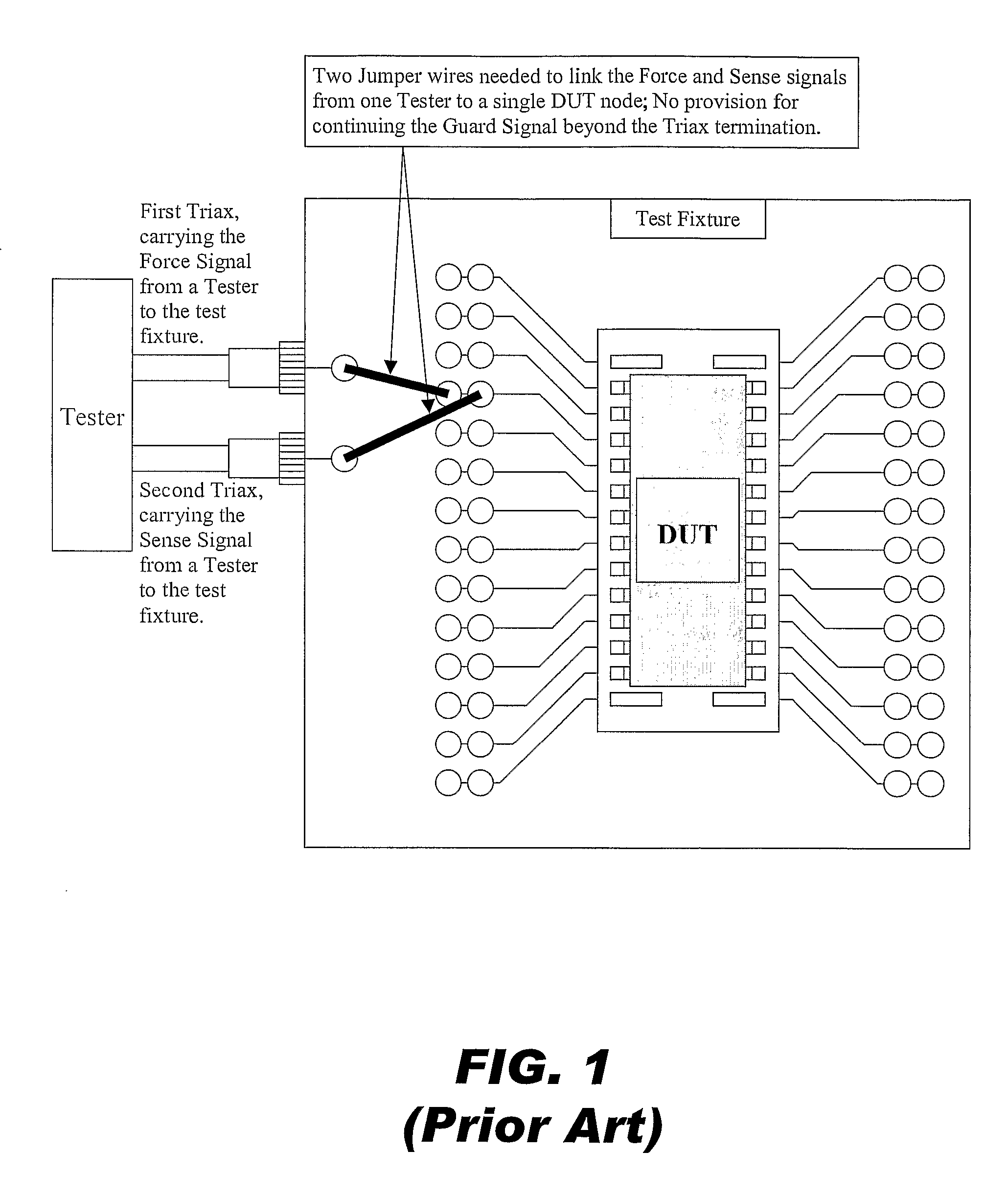
However, even with such two-Triax approach, there is a problem with the final connection within the Test Fixture.
Another problem with the two-Triax scheme is that the Force and Sense lines have to be individually “jumpered” one at a time to the same node.
If, by chance, a mistake is made and the Force lines goes to one node of the DUT while the Sense lines goes to another, then that would break the key feedback loop and may cause a voltage on the DUT far different from what was intended.
The possibility this error is heightened during tests that require the use of multiple Tester's.
Since the DUTs are commonly placed on a special fixture (hereinafter “Test Fixture”), these connecting wires may develop non-negligible Ohmic voltage drop due the flowing current, as well as leakage to their surrounding (neighboring wires in particular).
The stringent demands from state-of-the-art electronic device testing, in terms of accuracy, sensitivity and low-leakage current, over a wide range of current and voltage levels, make such connectivity issues both important and challenging.
Also, connecting the sense to the DUT assures measurement of the required voltage at the DUT, rather than the forcing signal, possibly affected by Ohmic losses along its connecting line.
However, even with such two-Triax approach, there is a problem with the final connection within the Test Fixture.

Method used


Image

  • Electrical connector for semiconductor device test fixture and test assembly
  • Electrical connector for semiconductor device test fixture and test assembly
  • Electrical connector for semiconductor device test fixture and test assembly

Examples


Embodiment Construction

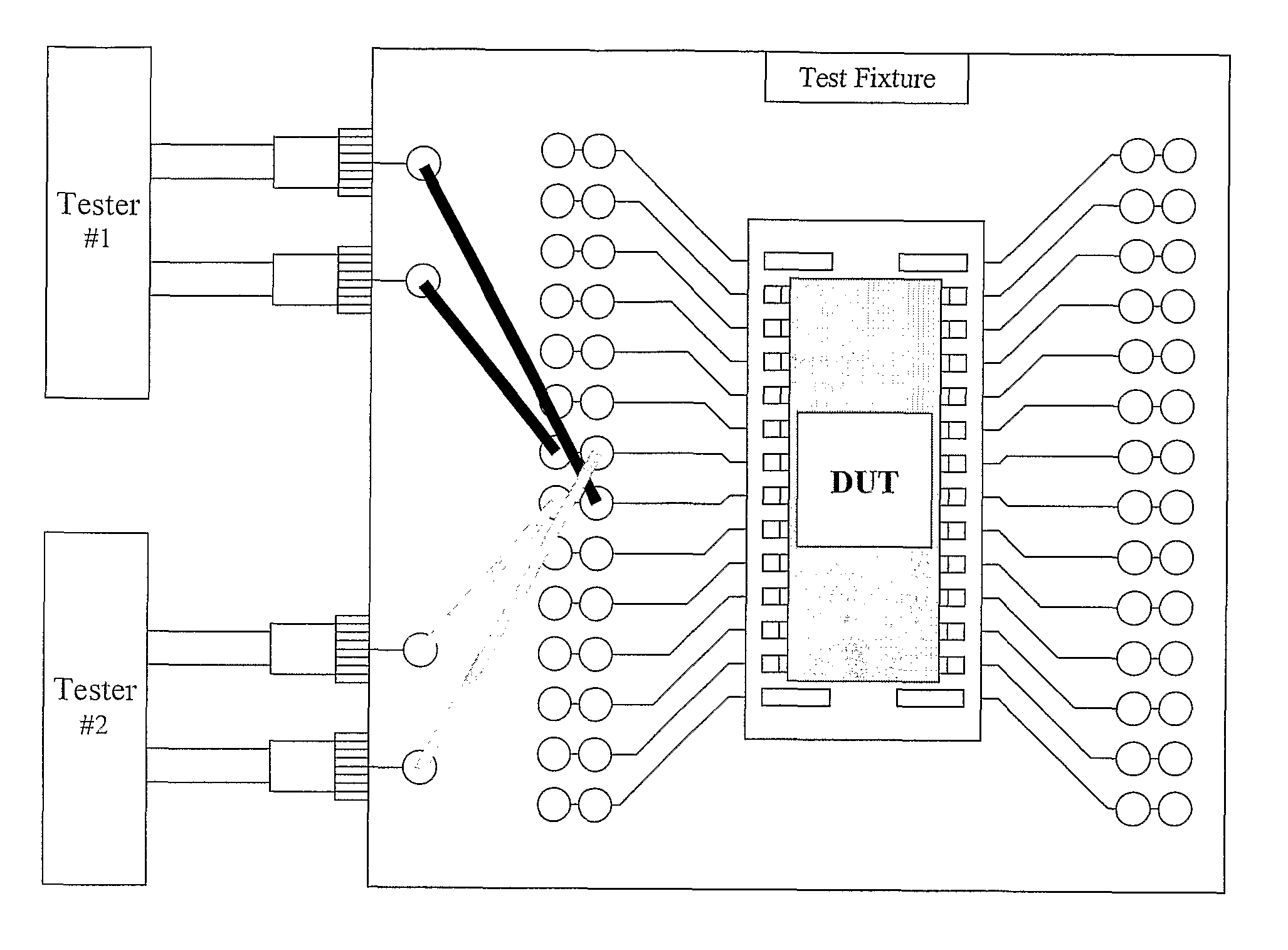
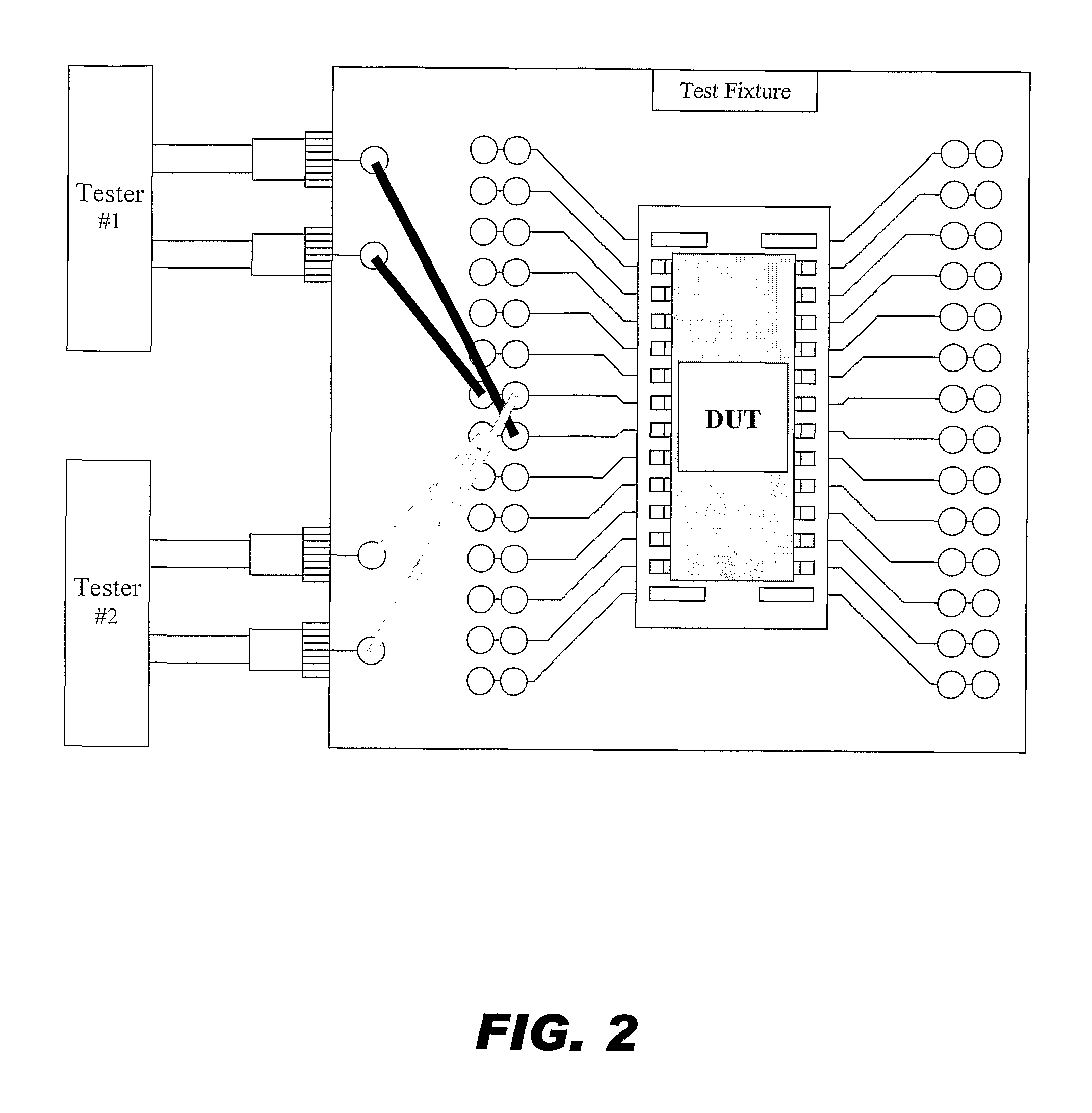
[0011] The first element in the current invention (FIG. 3) is the use of miniature cables that can carry at least the three critical signals, namely the Force, Sense, and Guard signals, in one cable instead of the two bulky Triax cables. The specific cables chosen by us are mini-USB cables, very common in computer related applications. These flexible, relatively cheap, readily available and physically small cables possess excellent insulation characteristics. Each cable contains five inner wires, all surrounded by a metallic enclosure. The five inner-wires are used as follows: One wire for Sense, one wire for Guard and the remaining three wires for Force. Note that three wires are allocated for the force signal to maximize its current carrying capability; however, any combination which assures at least one dedicated wire to each of the three functions (namely, Force, Sense, Guard) is applicable and should be considered an integral part of this invention. Another related provision ad...


PUM


Abstract

An interconnect assembly is for use in connection a semiconductor device under test (DUT) having a plurality of leads to electronic test equipment. The interconnect assembly includes a cable including a plurality of wires with a least one wire for sensing a signal from a DUT, at least one wire for a forcing signal to the DUT, and at least one wire for a guarding signal driven by the same electrical potential as the forcing signal. A male connector includes the plurality of wires, an outer metal coating surrounding the plurality of wires, and an insulating coating around the outer metal coating. A receptacle connector is for receiving the male connector and plurality of wires with corresponding contacts.

Description

BACKGROUND [0001] The electric wires connecting between the Device(s) Under-Test (DUT(s)) and the electronic equipment, which delivers the various electrical stimuli to the DUTs and measure them accordingly, require special attention, in particular when very sensitive devices are involved. Since the DUTs are commonly placed on a special fixture (hereinafter “Test Fixture”), these connecting wires may develop non-negligible Ohmic voltage drop due to the flowing current, as well as leakage to their surroundings. The stringent demands from state-of-the-art electronic device testing, in terms of accuracy, sensitivity and low-leakage current, over a wide range of current and voltage levels, make such connectivity issues both important and challenging. [0002] The most common approach to address these concerns is by using two tri-axial cables (hereinafter “Triax”) per each electronic stimulus, where both sensing the true voltage on the device nodes and minimizing the leakage are important ...

Claims


Application Information

Patent Timeline
Patent Type & Authority Applications(United States)
IPC IPC(8): H01R4/66H01R13/658
CPCH01R13/65807G01R1/06H01R24/562H01R2201/20H01R13/6586
Inventor CUEVAS, PETER P.
Owner QUALITAU
Learn More