Angular position and velocity estimation for synchronous machines based on extended rotor flux

Active Publication Date: 2007-08-23
HAMILTON SUNDSTRAND CORP
View PDF5 Cites 32 Cited by
  • Summary
  • Abstract
  • Description
  • Claims
  • Application Information

AI Technical Summary

Benefits of technology

[0004] The invention comprises a method of correcting the determination of extended rotor flux using a lag function and a correction algorithm that closely approximates a pure i

Problems solved by technology

However, in practice, a pure integrator suffers from direct current (DC) drifting, initial value holding, and even stability problems.
However, at low dyn

Method used


Image

  • Angular position and velocity estimation for synchronous machines based on extended rotor flux
  • Angular position and velocity estimation for synchronous machines based on extended rotor flux
  • Angular position and velocity estimation for synchronous machines based on extended rotor flux

Examples


Embodiment Construction

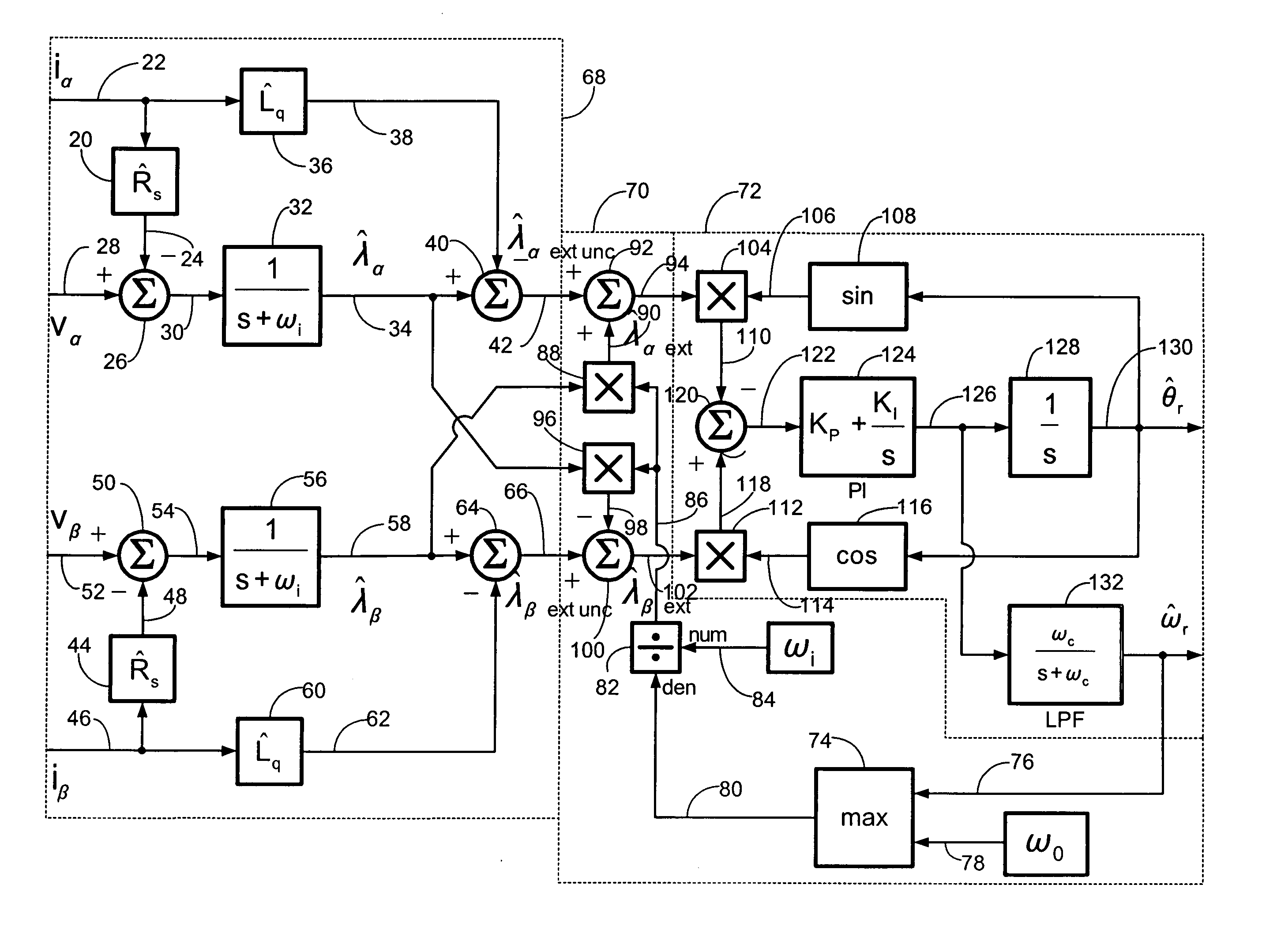
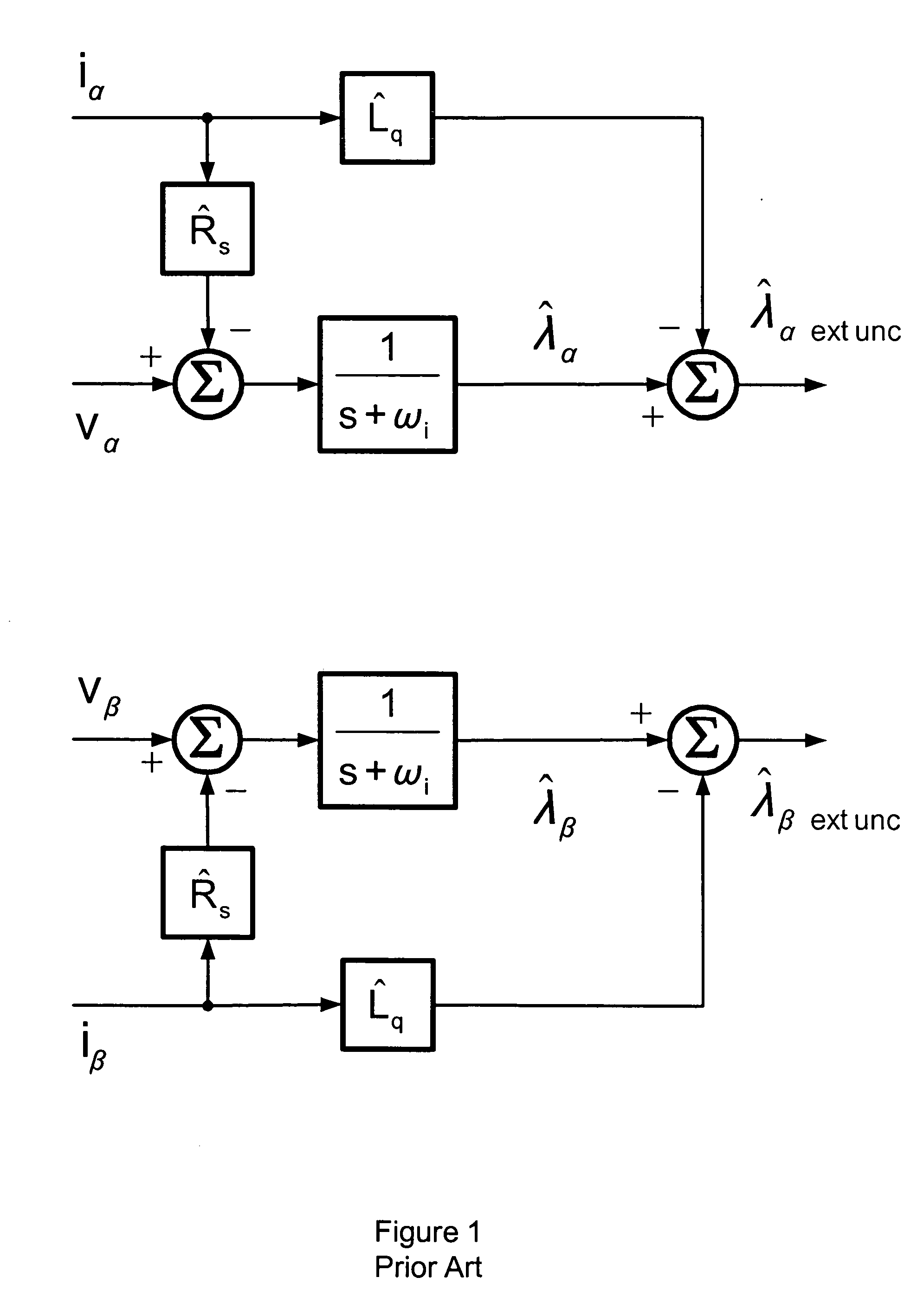
[0012] For Extended Flux Sensorless (EFS) control of a synchronous dynamoelectric machine, the following differential equations estimate the stator flux linkages in the α-β two-axis stationary reference frame using a lag approximation to a pure integrator: ⅆλ^αⅆt=vα-R^s×iα-ωefs×λ^α(1)ⅆλ^βⅆt=vβ-R^s×iβ-ωefs×λ^β(2)

where, [0013]λα−α-axis stator flux estimate: V-sec [0014]λβ=β-axis stator flux estimate; V-sec [0015] vα=α-axis stator potential; V [0016] vβ=β-axis stator potential; V [0017] iα=α-axis stator current; A [0018] iβ=β-axis stator current; A [0019] {circumflex over (R)}s=estimated stator resistance; Ohm [0020]ωi=lag function corner frequency; sec−1

[0021] For alternating current (AC) steady state analysis, the transformation of these differential equations into Laplace transform notation is: λ^α=vα-R^s×iαs+ωi(3)λ^β=vβ-R^s×iβs+ωi(4)

where [0022] s=Laplace operator; sec−1

[0023] The magnitudes of these two stator flux linkage estimates at an estimated electrical frequency Of {c...


PUM


Abstract

A method of correcting the determination of extended rotor flux using a lag function and a correction algorithm that closely approximates a pure integrator function to correct for lag function errors that can extend the EFS control down to dynamoelectric machine speeds corresponding to as low as 10 Hz electrical frequency.

Description

FIELD OF THE INVENTION [0001] The invention relates to rotor angular position and velocity sensing systems for mechanical shaft sensorless control of dynamoelectric machines, and more particularly to an improved system for resolving the position of a rotor for a dynamoelectric machine using an estimate of extended rotor flux. BACKGROUND OF THE INVENTION [0002] As the aerospace industry moves into the more electric era, inverter controlled dynamoelectric machine drives become more common onboard aircraft. Next generation dynamoelectric machine controllers must meet many new system and design challenges including cost reduction and reliability improvement. Shaft sensorless dynamoelectric machine control holds great promise for meeting these challenges. [0003] An aircraft generator is usable as a motor for engine starting when powered by an inverter. To reduce cost and improve reliability, it is very desirable to eliminate the mechanical shaft sensor for the engine starter. A novel sen...

Claims


Application Information

Patent Timeline
IPC IPC(8): H02P1/46
CPCH02P21/06Y10S388/911H02P21/14
Inventor MARKUNAS, ALBERT L.
Owner HAMILTON SUNDSTRAND CORP
Why Eureka
Try Eureka