Current mirror with improved output impedance at low power supplies

a technology of output impedance and current mirror, which is applied in the direction of electric variable regulation, process and machine control, instruments, etc., can solve the problems of reducing the power supply vsub>dd /sub>imping upon the upper range of headroom available, and achieves high output impedance, increase the available headroom, and increase the effect of headroom

Inactive Publication Date: 2007-08-23
CISCO TECH INC +1
View PDF8 Cites 8 Cited by
  • Summary
  • Abstract
  • Description
  • Claims
  • Application Information

AI Technical Summary

Benefits of technology

[0013]In accordance with the present invention, a common mode voltage regulator circuit is utilized in con junction with the output branch of the current mirror to eliminate the need for an additional active device in series with the cascode output transistor to control the output voltage. The elimination of this active device thus increases the available headroom for the output branch—particularly advantageous for low voltage applications—yet maintains the high output impedance required for accurate mirroring of the input current.
[0014]In an MOS-based embodiment of the present invention, one MOS device along the output branch of the current mirror is eliminated (thus increasing the available headroom by one VDS) and the drain voltage at the remaining MOS device (i.e., VOUT) is controlled by adjusting the common mode output voltage of the input circuit branch. The arrangement of the present invention may be cascaded to form a multi-stage circuit or, alternatively, may be utilized in conjunction with prior art current mirrors to achieve even greater output impedance values when larger supply voltages are present.

Problems solved by technology

However, reducing the power Supply VDD impinges upon the upper range of the headroom available to the load circuit.

Method used


Image

  • Current mirror with improved output impedance at low power supplies
  • Current mirror with improved output impedance at low power supplies
  • Current mirror with improved output impedance at low power supplies

Examples


Embodiment Construction

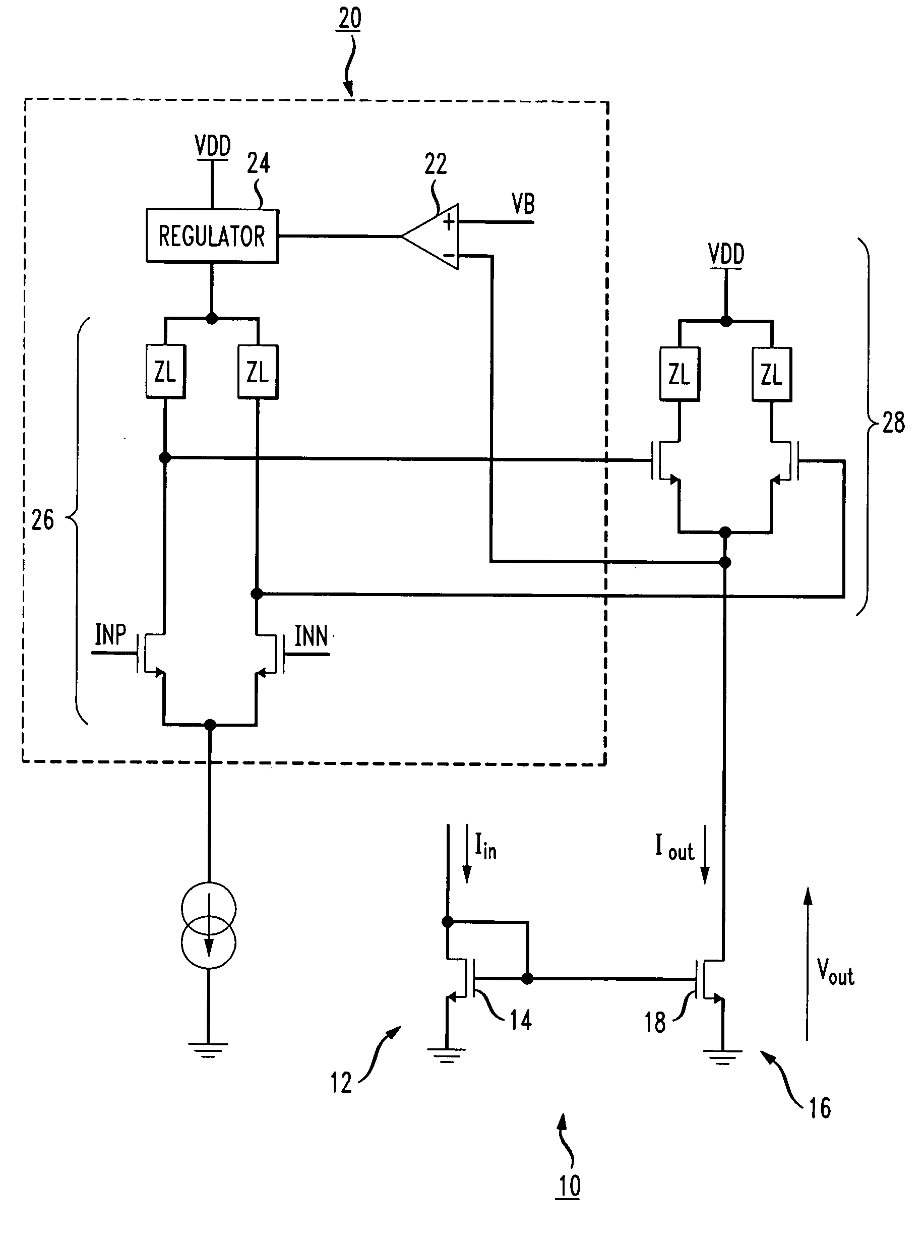
[0026]FIG. 5 illustrates an exemplary current mirror circuit 10 formed in accordance with the present invention to provide a high output impedance when used in situations powered by a relatively low voltage (on the order of, for example, VDD=1.2 V or less). Current mirror 10 includes a reference branch 12 including an input reference transistor 14 that is diode-connected (that is, with the drain of transistor 14 coupled to the gate of transistor 14). Input current Iin is shown as coupled into the drain input of input reference transistor 14. As with the prior art arrangements discussed above, current mirror 10 includes an output branch 16 along which the input current is “mirrored” to provide an output current for passing through a load. Output cascode transistor 18 is shown along output branch 16.

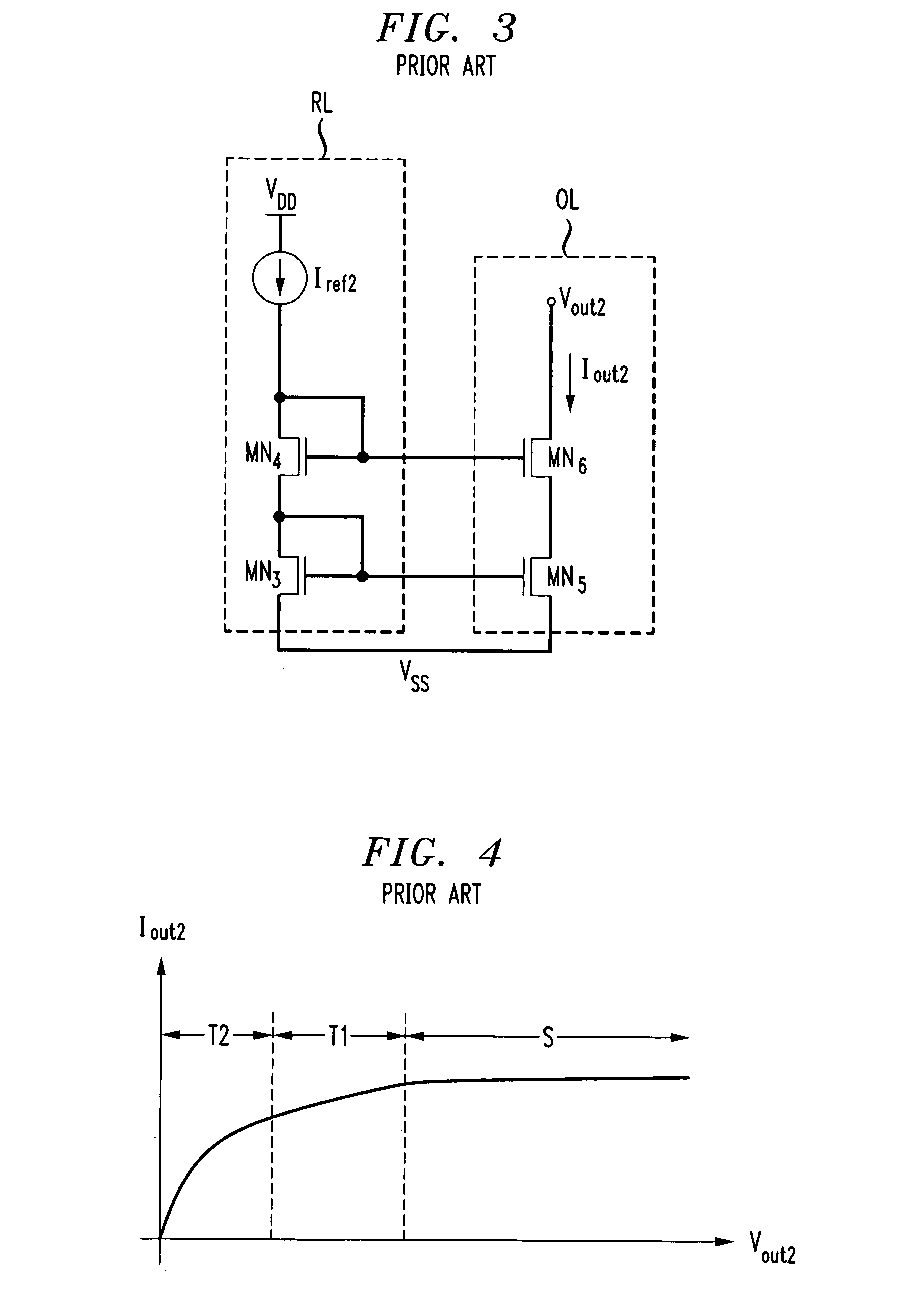
[0027]Comparing the arrangement of inventive current mirror circuit 10 to prior art mirror 3, it is apparent that transistor MN6 of prior art arrangement 3 has been eliminated from the out...


PUM


Abstract

A current mirror circuit arrangement is formed to maintain a high output impedance when utilized with a relatively low voltage power supply. A common mode voltage regulator circuit is utilized in conjunction with the output branch of the current mirror to eliminate the need for an additional active device in series with the output transistor of a current mirror to control its drain voltage. The elimination of the second active device thus increases the available headroom for the output branch (i.e., adds one VDS). The increased headroom in the inventive current mirror is particularly advantageous for low voltage applications, since it is capable of maintaining the high output impedance required for accurate mirroring of the input current.

Description

CROSS-REFERENCE TO RELATED APPLICATION[0001]This application claims the benefit of U.S. Provisional Application 60 / 774,944, filed Feb. 17, 2006.TECHNICAL FIELD[0002]The present invention relates to a current mirror arrangement and, more particularly, to a current mirror circuit that maintains a high output impedance when utilized with a relatively low voltage power supply.BACKGROUND OF THE INVENTION[0003]There are many techniques used to provide regulated current to a load circuit. One technique involves a current mirror. A conventional current mirror provides output current proportional to an input current. Separation between the input and output current ensures that the output current can drive high impedance loads. Conventional current mirror designs have been implemented in both bipolar and MOS technology. MOS devices with short channel lengths (and therefore faster operation) have provided an impetus toward current mirrors based on MOS technology.[0004]An important aspect in de...

Claims


Application Information

Patent Timeline
Patent Type & Authority Applications(United States)
IPC IPC(8): G05F1/10
CPCG05F3/262
Inventor MOSINSKIS, PAULIUS MINDAUGAS
Owner CISCO TECH INC
Why Eureka
Try Eureka