Electromagnetic switch

a technology of electromagnetic switch and spring constant, which is applied in the direction of magnets, contact mechanisms, magnets, etc., can solve the problems of large impact noise or a large crashing sound, impact noise becomes an obstacle, etc., and achieves small spring constant, reduce spring constant, and increase damping (or attenuation coefficient

Inactive Publication Date: 2007-08-23
DENSO CORP
View PDF8 Cites 36 Cited by
  • Summary
  • Abstract
  • Description
  • Claims
  • Application Information

AI Technical Summary

Benefits of technology

[0018]In the electromagnetic switch according to another aspect of the present invention, a slit or a hole which penetrates toward the lamination direction is formed in at least one metal plate in order to reduce its spring constant or to increase its damping (or its attenuation) coefficient rather than that of the other metal plates. Because the slit or the hole is formed in at least one metal plate in order to have a small spring constant or a larger damping (or a larger attenuation) coefficient, it is possible to reduce the impact force when the movable iron core is attracted by the energized electromagnet and collides with the base part in the stationary iron core, and thereby to reduce the crashing sound when the movable iron core collides with the stationary iron core.
[0019]In the electromagnetic switch according to another aspect of the present invention, a surface treatment or a lubrication treatment is performed on the surface of at least one metal plate in order to have a smaller coefficient of friction than the coefficient of friction of other metal plates. Because the surface treatment or the lubrication treatment for the surface of the metal plate can reduce the coefficient of friction of the surface of the metal plate and reduces the friction between the surfaces of the laminated metal plates faced to each other, the metal plates become flexibility when the impact force is applied to the base part, for example, when the movable iron core collides with the stationary iron core. As a result, this configuration increases the impact absorption (or damping) capability of the stationary iron core and reduces the impact noise or crashing sound when the movable iron core collides with the stationary iron core.
[0020]In the electromagnetic switch according to another aspect of the present invention, the base part is composed of the metal plate of ferroma...

Problems solved by technology

However, a conventional electromagnetic switch causes a large impact noise or a large crashing sound when the plunger is attracted to and...

Method used


Image

  • Electromagnetic switch
  • Electromagnetic switch
  • Electromagnetic switch

Examples


first embodiment

[0039]A description will be given of the electromagnetic switch according to the first embodiment of the present invention with reference to FIG. 1 to FIG. 4.

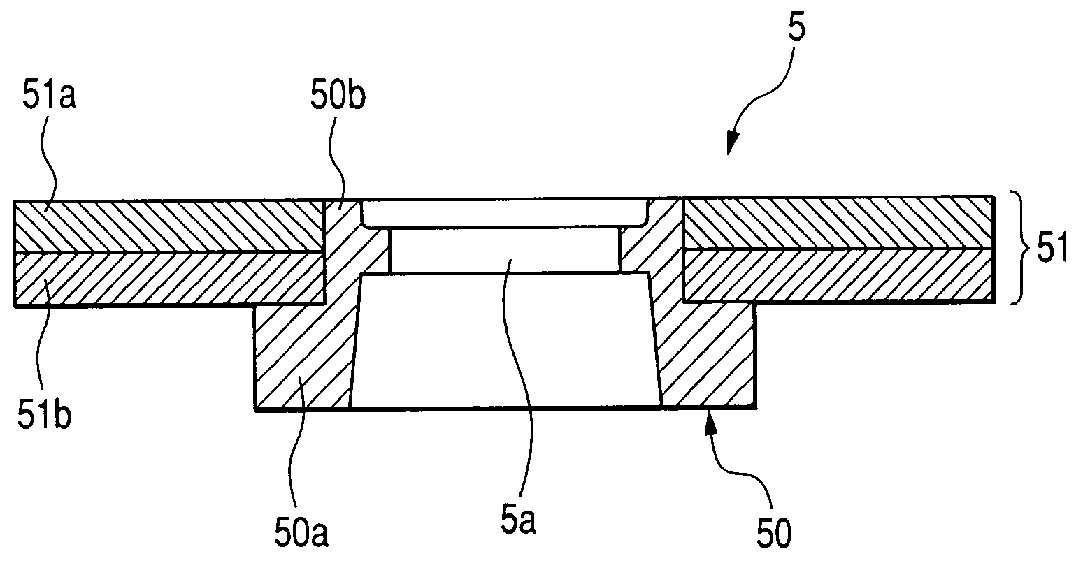
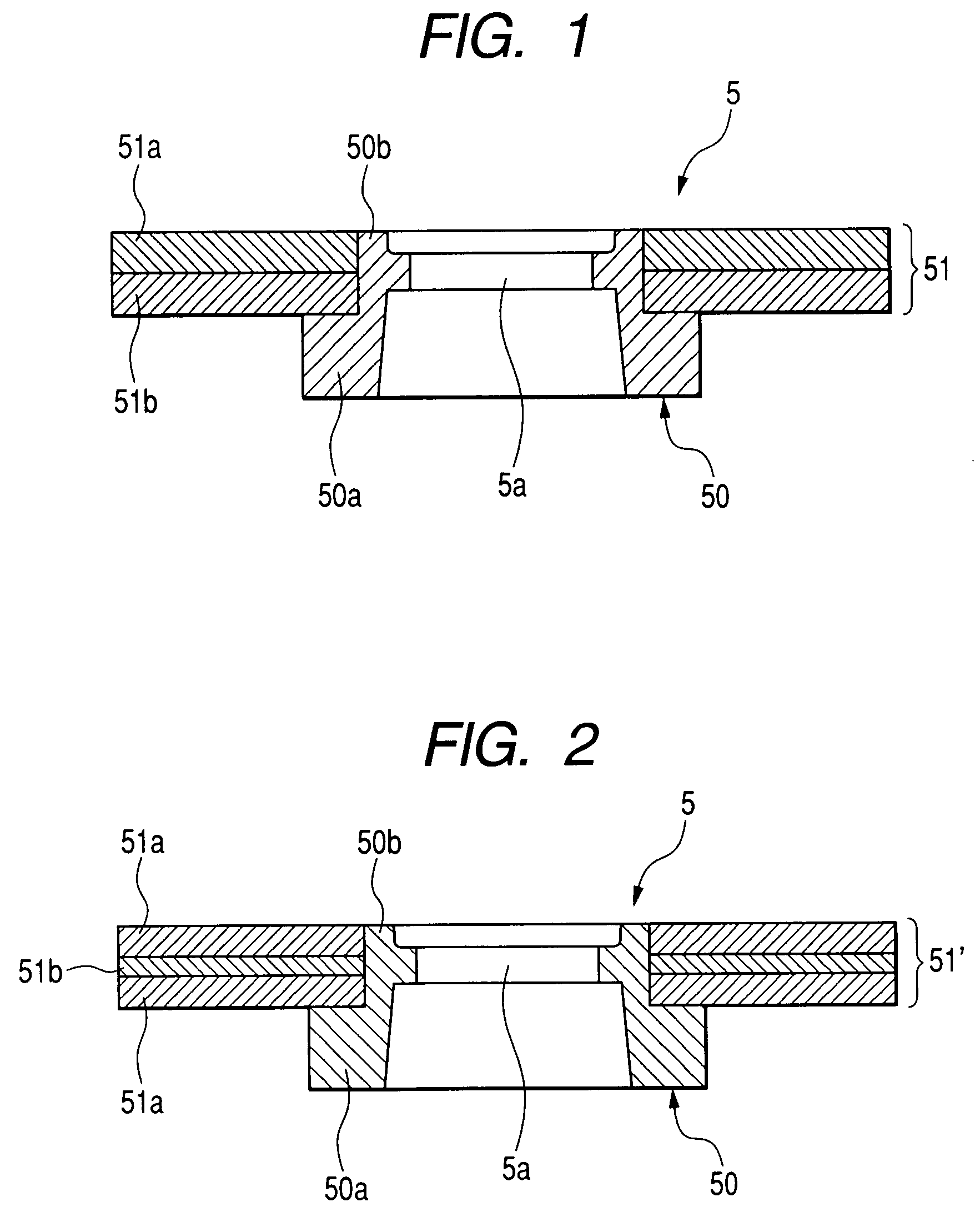
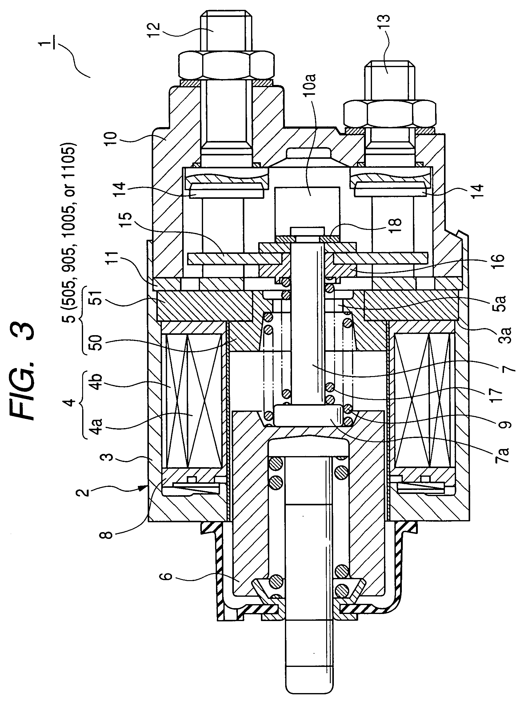
[0040]FIG. 1 is a sectional view showing a configuration of a stationary iron core 5 of the electromagnetic switch 1 according to the first embodiment of the present invention. FIG. 2 is a sectional view showing another configuration of the stationary iron core 5 of the electromagnetic switch 1 according to the first embodiment. FIG. 3 is a sectional view showing an entire configuration of the electromagnetic switch 1 according to the first embodiment.

[0041]The electromagnetic switch 1 according to the first embodiment is applied to a starter (not shown) mounted on a vehicle, for example. The starter is capable of starting an internal combustion engine mounted on the vehicle. As shown in FIG. 3, the electromagnetic switch 1 has a solenoid 2 forming an electromagnet by which a main contact, described later in detail, mounted on ...

second embodiment

[0061]A description will be given of the electromagnetic switch according to the second embodiment of the present invention with reference to FIG. 5 and FIGS. 6A and 6B.

[0062]FIG. 5 is a sectional view showing a configuration of the stationary iron core 505 in the electromagnetic switch according to the second embodiment of the present invention. FIG. 6A is a plan view showing a configuration of the metal plate 551a having slits 52, and FIG. 6B is a plan view showing a configuration of the metal plate 552a′ having holes 53.

[0063]As shown in FIG. 5, the disk part 551 forming the stationary iron core 505 in the electromagnetic switch according to the second embodiment is composed of a plurality of metal plates (for example, iron plates) that are laminated. In the configuration shown FIG. 5, the stationary iron core 505 has a pair of the metal plates 551a. Further, at least one metal plate 551a has slits 52, as shown in FIG. 6A, or at least one metal plate 551a′ has holes 53, as shown ...

third embodiment

[0068]A description will be given of the electromagnetic switch according to the third embodiment of the present invention with reference to FIG. 7 and FIG. 8.

[0069]FIG. 7 is a partial view showing a configuration of the electromagnetic switch according to the third embodiment of the present invention. FIG. 8 is a plan view showing a configuration of a disk part 751 forming the stationary iron core in the electromagnetic switch according to the third embodiment.

[0070]As shown in FIG. 7, each of the plural metal plates forming the disk part 751 of the stationary iron core has the slits 52 or the holes 53s, like the configuration of the second embodiment which has been explained with reference to FIGS. 6A and 6B. Further, a plurality of the plural metal plates 551a (see FIG. 6A) or 551a′ (see FIG. 6B) are laminated and the plural silts 52 (or the holes 53) form penetrating holes which penetrate through the entire of the plural metal plates 551a (see FIG. 6A) or 551a′ (see FIG. 6B). It...


PUM


Abstract

In an electromagnet switch, a stationary iron core is composed mainly of a base part and a disk part. The base part is faced to a plunger and the disk part is forcedly inserted and fixed to a boss part formed in the base part. The disk part is composed of a metal plate of ferromagnetic substance (iron plate) and another substance plate (made of resin or rubber and the like, for example,) of a smaller spring constant or a larger damping coefficient than that of the metal plate. The metal plate and another substance plate are laminated. Another substance plate absorbs or reduces the impact force when the plunger is electromagnetically attracted toward and collides with the base part. The propagation of a large impact noise or crashing sound is thereby suppressed, and as a result the impact noise can be reduced.

Description

CROSS-REFERENCE TO RELATED APPLICATIONS[0001]This application is related to and claims priority from Japanese Patent Applications No. 2006-47026, filed on Feb. 23, 2006, No. 2006-181362, filed on Jun. 30, 2006, and No. 2006-231875, filed on Aug. 29, 2006, the contents of which are hereby incorporated by reference.BACKGROUND OF THE INVENTION[0002]1. Field of the Invention[0003]The present invention relates to an electromagnetic switch capable of turning on and turning off an electric contact mounted on an energized electric circuit of a starter motor.[0004]2. Description of the Related Art[0005]In order to satisfy recent demand of reducing the fuel consumption for saving energy in vehicles, an automatic engine-stop system is adopted to many vehicles. For example, when a driver stops his vehicle at an intersection when the stop lamp (red or yellow lamp) of a traffic signal is lighting, the automatic engine-stop system mounted on the vehicle controls so that the vehicle is automaticall...

Claims


Application Information

Patent Timeline
IPC IPC(8): H01H67/02
CPCH01H51/065H01H50/305
Inventor KURASAWA, TADAHIROUSAMI, SHINJITERAMACHI, TOMOHIRO
Owner DENSO CORP
Why Eureka
Try Eureka