RFID reader and method for removing a transmission carrier leakage signal

Active Publication Date: 2007-08-23
SAMSUNG ELECTRONICS CO LTD
View PDF10 Cites 57 Cited by
  • Summary
  • Abstract
  • Description
  • Claims
  • Application Information

AI Technical Summary

Benefits of technology

[0023]The present invention has been developed in order to address the above drawbacks and other problems associated with the related arrangement. An aspect of the present invention is to provide an RFID reader which can so

Problems solved by technology

As a result, problems of signal deterioration and DC offset may occur.
In addition, the errors may become greater due to the difference between the bidirectio

Method used


Image

  • RFID reader and method for removing a transmission carrier leakage signal
  • RFID reader and method for removing a transmission carrier leakage signal
  • RFID reader and method for removing a transmission carrier leakage signal

Examples


Example

[0039]Certain exemplary embodiments of the present invention will be described in greater detail with reference to the accompanying drawings.

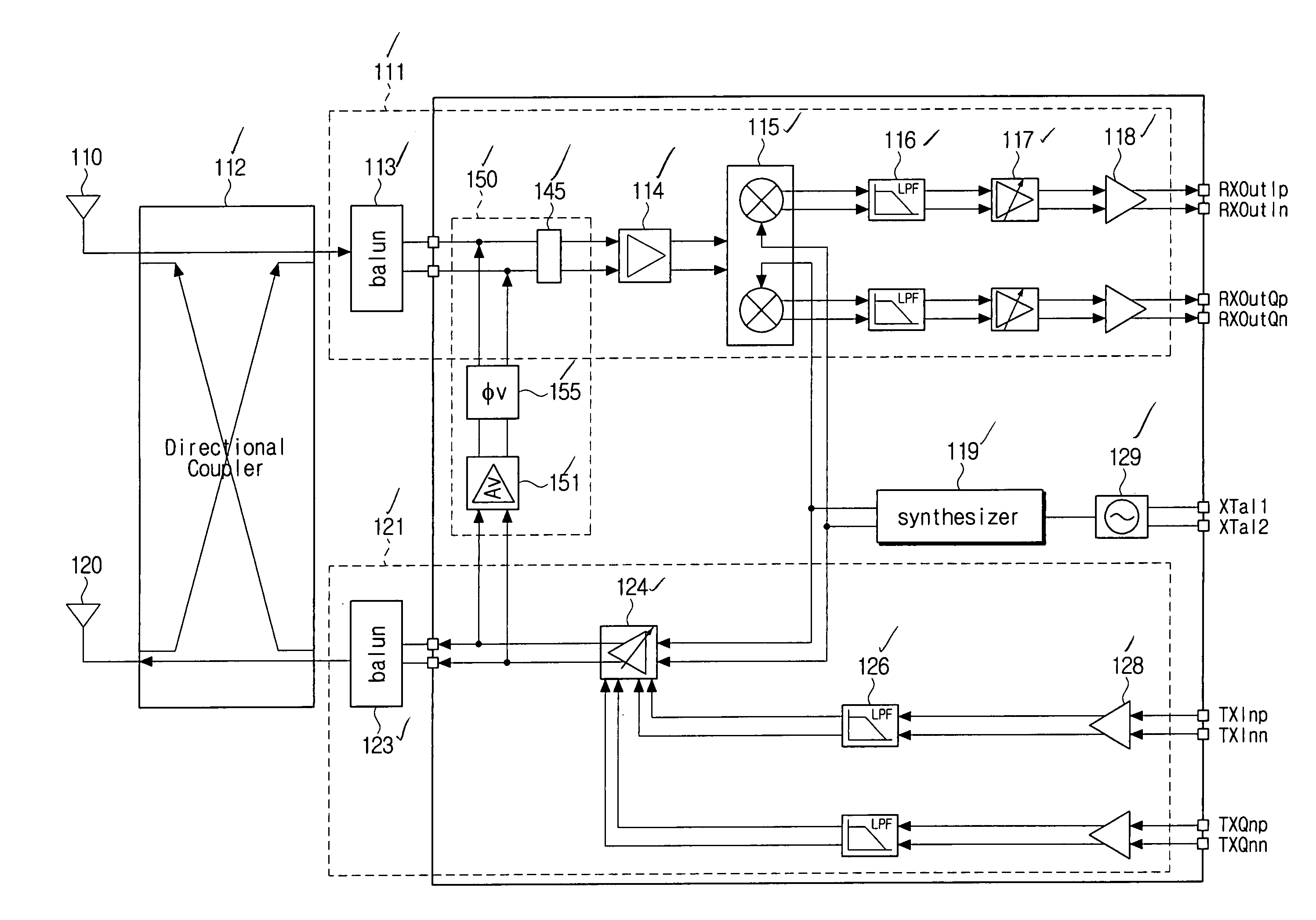
[0040]FIG. 4 is a circuit diagram of an RFID reader having a leakage removing circuit 150 according to an exemplary embodiment of the present invention.

[0041]As illustrated in FIG. 4, the RFID reader according to the present invention includes a transmitting circuit 121, a receiving circuit 111, a leakage removing circuit 150, and directional coupler 112.

[0042]The transmitting circuit 121 includes a pair of input buffers 128, a pair of low pass filters (LPFs) 126, a variable amplifier 124, and a balun 123.

[0043]The respective input buffers 128 amplify quadrature signals (i.e., I-signal and Q-signal) from a processing circuit (not illustrated) that controls transmission, and generate a transmitted signal at a specified level. The respective LPFs 126 filter the quadrature signals (i.e., I-signal and Q-signal) from the respective buffers 128, and ...


PUM


Abstract

A radio frequency identification (RFID) reader is provided, having a transmitting circuit that generates a transmitted signal to operate an RFID tag, a receiving circuit that receives a received signal including a tag signal from the RFID tag and a transmission carrier leakage signal leaking from the transmitting circuit, and a leakage removing circuit that senses a phase and amplitude of the transmission carrier leakage signal inputted to the receiving circuit, converts the transmitted signal from the transmitting circuit into a signal having a phase opposite to that of the transmission carrier leakage signal and an amplitude equal to that of the transmission carrier leakage signal, and synthesizes the converted signal and the received signal inputted to the receiving circuit.

Description

CROSS REFERENCE TO RELATED APPLICATIONS[0001]This application claims priority from Korean Patent Application No. 10-2006-0011021, filed on Feb. 6, 2006, in the Korean Intellectual Property Office, the disclosure of which is incorporated herein by referenceBACKGROUND OF THE INVENTION[0002]1. Field of the Invention[0003]Apparatuses and methods consistent with the present invention relate to a radio frequency identification (RFID) reader, and more particularly, to an RFID reader which addresses problems of signal deterioration and DC offset by effectively removing a transmission carrier leakage signal being inputted from a transmitting circuit to a receiving circuit, and which has a simple circuit construction.[0004]2. Description of the Related Art[0005]A ubiquitous sensor network (USN) has recently received a lot of attention as the basic infrastructure for realizing a ubiquitous society, which is one of the big issues in the information and communication field. The USN is a technolo...

Claims


Application Information

Patent Timeline
IPC IPC(8): H04Q5/22
CPCG06K7/0008H04B1/59H04B1/525G06K17/00
Inventor BANG, HEE-MUNEO, YUN-SEONGKWON, ICK-JINLEE, HEUNG-BAE
Owner SAMSUNG ELECTRONICS CO LTD
Why Eureka
Try Eureka