Auto-Adjusting Device and Method for Adjusting Drive Voltage Light Receiver

a technology of light receiver and drive voltage, which is applied in the direction of material analysis, photometry using electric radiation detectors, instruments, etc., can solve the problems affecting the stability and ability of distance measurement of ranger finders, and achieve the effect of not complicated circuit construction and advantageous assembly and manufacturing costs

Inactive Publication Date: 2016-06-30
ASIA OPTICAL INT LTD +1
View PDF1 Cites 0 Cited by
  • Summary
  • Abstract
  • Description
  • Claims
  • Application Information

AI Technical Summary

Benefits of technology

[0006]An object of the invention is to provide an auto-adjusting device and method for adjusting a drive voltage of a light receiver. The drive voltage of the light receiver is adjusted in accordance with temperature variations so that the light receiver can be maintained in a stable condition under wide range variation of temperature. Also, the circuit construction of the invention is not complicated, which is advantageous in assembly and manufacturing cost.

Problems solved by technology

When an avalanche photodiode of a range finder is driven by a fixed high voltage, the gain of the avalanche photodiode and the magnitude of output signals may vary due to the environmental temperature variations, which may affect the stability and ability of distance measurement of the ranger finder.

Method used


Image

  • Auto-Adjusting Device and Method for Adjusting Drive Voltage Light Receiver
  • Auto-Adjusting Device and Method for Adjusting Drive Voltage Light Receiver
  • Auto-Adjusting Device and Method for Adjusting Drive Voltage Light Receiver

Examples


Embodiment Construction

[0023]The following description is of the best-contemplated mode of carrying out the invention. This description is made for the purpose of illustrating the general principles of the invention and should not be taken in a limiting sense. The scope of the invention is best determined by reference to the appended claims.

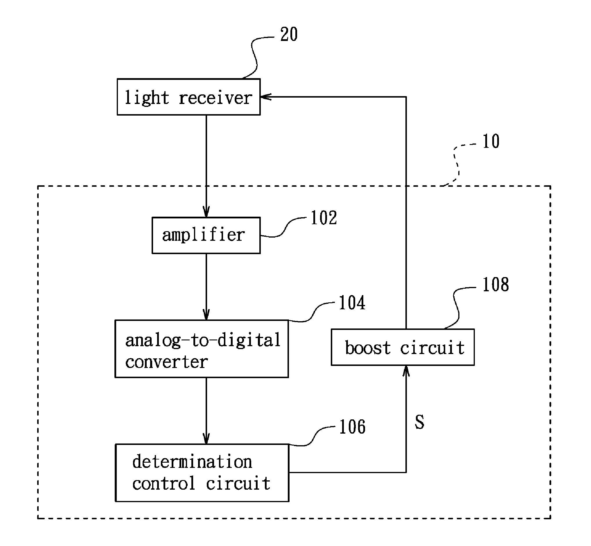
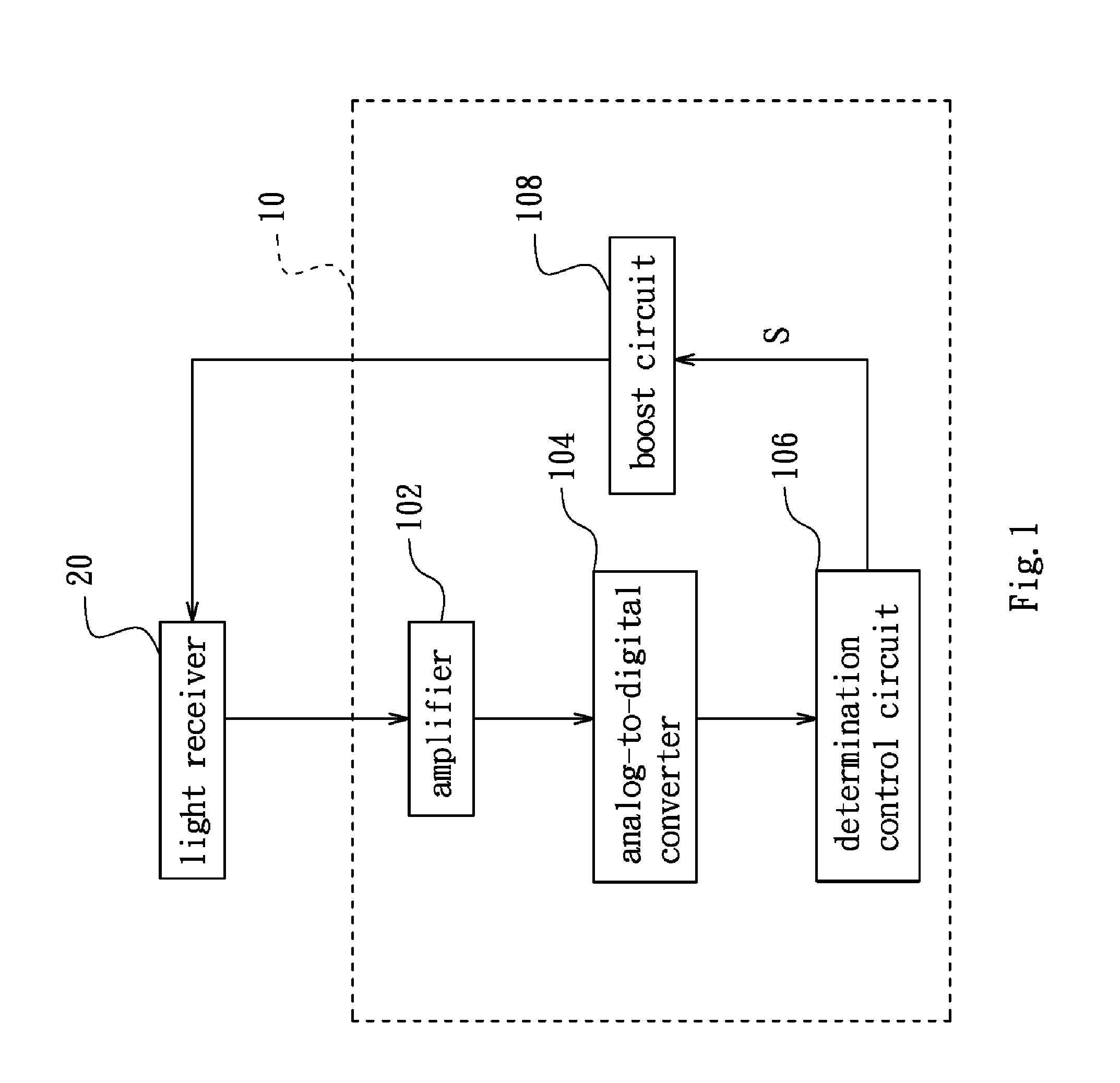
[0024]Referring to FIG. 1, an auto-adjusting device 10 of the invention is coupled to a light receiver 20 to automatically adjust the drive voltage of the light receiver 20 so that the light receiver 20 can work under a high gain condition without being affected by temperature. In this embodiment, the light receiver 20 is an avalanche photodiode (APD).

[0025]The auto-adjusting device 10 of the invention includes an amplifier 102, an analog-to-digital converter (ADC) 104, a determination control circuit 106 and a boost circuit 108. In operation, the light receiver 20 receives light and generates photocurrent which is an analog signal. The analog signal is amplified by th...


PUM


Abstract

An auto-adjusting device for adjusting a drive voltage of a light receiver includes an amplifier, an analog-to-digital converter, a determination control circuit and a boost circuit. The amplifier is configured to amplify an analog signal generated by the light receiver. The analog-to-digital converter is configured to convert the amplified analog signal to a digital signal. The determination control circuit is configured to process and determine the digital signal, and output a control signal when the processed digital signal satisfies a predetermined condition. The boost circuit is configured to receive the control signal and adjust the drive voltage of the light receiver.

Description

BACKGROUND OF THE INVENTION[0001]1. Field of the Invention[0002]The invention relates to an auto-adjusting device and method for adjusting a drive voltage of a light receiver.[0003]2. Description of the Related Art[0004]An avalanche photodiode working under a high gain condition is necessarily provided with a drive voltage near a breakdown point. When an avalanche photodiode of a range finder is driven by a fixed high voltage, the gain of the avalanche photodiode and the magnitude of output signals may vary due to the environmental temperature variations, which may affect the stability and ability of distance measurement of the ranger finder.BRIEF SUMMARY OF THE INVENTION[0005]If an avalanche photodiode is required to work at a high temperature, a high drive voltage must be provided for the avalanche photodiode to maintain the high gain condition. Therefore, an auto-adjusting device is needed to prevent the avalanche photodiode from damage due to an over-high drive voltage when the ...

Claims


Application Information

Patent Timeline
Patent Type & Authority Applications(United States)
IPC IPC(8): H01L31/02
CPCH01L31/02027G01J1/44
Inventor LI, SONGLAN, QI
Owner ASIA OPTICAL INT LTD
Why Eureka
Try Eureka