Nightlight Driving Device

Inactive Publication Date: 2012-07-26
LAI LI CHUN
View PDF2 Cites 0 Cited by
  • Summary
  • Abstract
  • Description
  • Claims
  • Application Information

AI Technical Summary

Benefits of technology

[0007]An objective of the present invention is to provide a nightlight driving device which can effectively

Problems solved by technology

However, for the aforementioned driving circuit, the voltage stabilizing module 15 and triode 18 still consume electrical energy in a consistent fashion even located in an environment of strong intensity of light during daytime, which, in the new generation emphasizing the aspects of low carbon trace, green energy and e

Method used


Image

  • Nightlight Driving Device
  • Nightlight Driving Device
  • Nightlight Driving Device

Examples


Embodiment Construction

[0018]The aforementioned and other technical contents, aspects and effects in relation with the present invention can be clearly appreciated through the detailed descriptions concerning the preferred embodiments of the present invention in conjunction with the appended drawings.

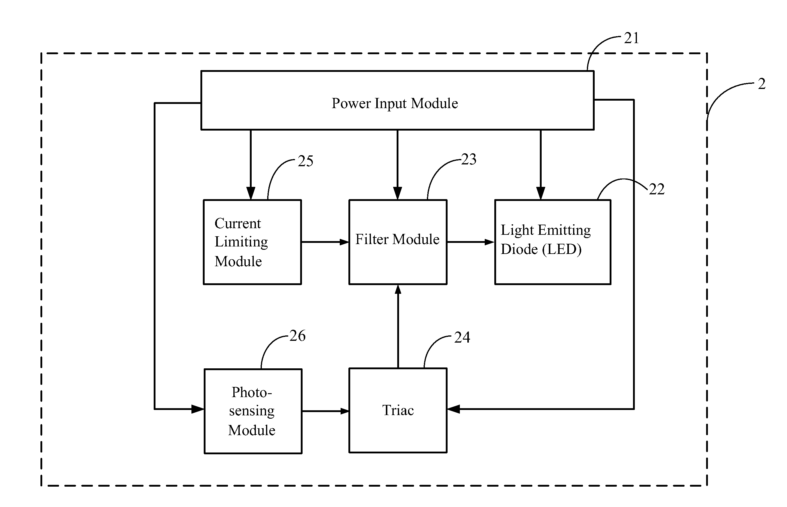
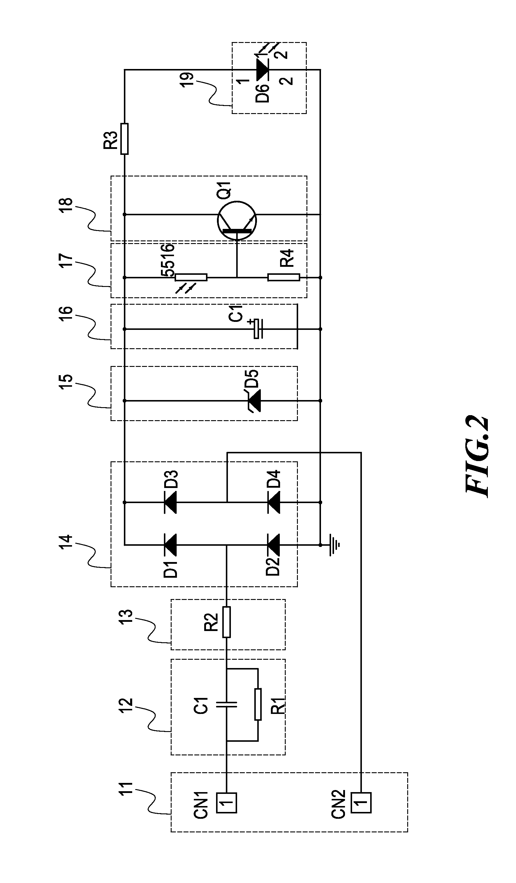
[0019]Refer now to FIGS. 3 and 4, wherein a diagram of integral architecture and a diagram of circuit implementation for the nightlight driving device according to the present invention are shown, and it can be seen that the nightlight driving device 2 comprises:

[0020]a power input module 21, used to provide the electric power required for entire operations and able to input a current;

[0021]a light emitting diode (LED) 22, connected to the power input module 21 in order to illuminate;

[0022]a filter module 23, respectively connected to the power input module 21 and the LED 22 and capable of inputting a stable current into the LED 22;

[0023]a triac 24, respectively connected to the power input module 21 and the ...


PUM


Abstract

A nightlight driving device is disclosed, comprising a power input module, a current limiting module, a triac, a photo-sensing module, a filter module and a light emitting diode (LED), wherein the filter module inputs a stable current into the LED and the power input module provides the power required for entire operations; therefore, when the photo-sensing module is located in a daytime environment, the photo-sensing module causes the triac not to be driven to conduct and the LED can not illuminate; on the other hand, in case the photo-sensing module is in a nighttime environment, the triac can be driven to conduct thereby enabling illumination of the LED so as to effectively save the power consumed by the nightlight.

Description

BACKGROUND OF THE INVENTION[0001]1. Field of the Invention[0002]The present invention relates to a nightlight driving device; in particular, it relates to a driving device which effectively simplifies the circuitry construction and saves the power consumed by the nightlight.[0003]2. Description of Related Art[0004]A driving device 1 for the commercially available nightlight at present days is shown in FIGS. 1 and 2, comprising a power input module 11, a resistance-capacitance buck module 12, a current limiting module 13, a current rectifying module 14, a voltage stabilizing module 15, a filter module 16, a photo-sensing module 17 having a photosensitive resistor, a triode 18 and a light emitting diode (LED) 19, wherein the triode 18 is respectively connected to the photo-sensing module 17 and the LED 19, and the power input module 11 provides the electric power required for entire operations. Hence, in case that the photosensitive resistor in the photo-sensing module 17 detects the ...

Claims


Application Information

Patent Timeline
IPC IPC(8): H05B37/02
CPCH05B33/0854H05B45/12
Inventor LAI, LI-CHUN
Owner LAI LI CHUN
Why Eureka
Try Eureka