Circuit and method for faster frequency switching in a phase locked loop

a phase locking loop and circuit technology, applied in pulse automatic control, oscillation generators, resonance circuit tuning, etc., can solve the problems of inability to adequately and reliably suppress spurious signals, and cannot be solved, so as to achieve sufficient suppression of spurious signals and simple and economical circuit arrangement and method steps

Active Publication Date: 2006-10-31
ATMEL GERMANY +1
View PDF13 Cites 6 Cited by
  • Summary
  • Abstract
  • Description
  • Claims
  • Application Information

AI Technical Summary

Benefits of technology

[0012]It is preferred according to the invention that the change of the output voltage of the loop filter is controlled in such a manner that the final value of the output voltage approximately corresponds to the value that arises after the circuit has fully settled to a new frequency caused by the change of the divider ratio. Through this feature, the VCO frequency is pushed or shifted into the region of the expected final value in a controlled manner in connection with the controlled switching of the divider ratio. If the remaining frequency error that still exists thereafter is sufficiently small, then the phase locked loop can pull-in and settle to the true final value in a relatively short time. In other words, the settling process is accelerated or given a “jump start” in a positively enforced manner. Thereby it is achieved, that even with an integer PLL circuit, a large frequency jump can be carried out in a time that is compatible with the GPRS requirements.
[0013]It is further preferred according to the invention, that the first frequency divider and the second frequency divider are controlled for a frequency change by the same common control signal that is also provided to the regulating signal generator. Furthermore, the regulating signal generator is designed and embodied so that it provides a predetermined output signal in response to and dependent on the received control signal. Through this common controlled switching of both frequency dividers and the regulating signal generator, a synchronization is achieved, which reduces interference in the following comparison of the output signals of the two frequency dividers in the phase / frequency detector. Through the above described design or embodiment of the regulating signal generator, the VCO can be provided with an immediately effective (i.e. without delay) base value synchronously with the controlled switching of the frequency divider or dividers. This reduces a frequency deviation in the phase / frequency detector.
[0014]Another preferred embodiment feature of the invention is that the regulating signal generator changes or varies the output voltage of the loop filter by tapping into or influencing the charge pump. Through this feature of the invention, the charge pump, which is present in the circuit anyway, is used to achieve a rapid controlled adaptation of the loop filter to the new required voltage output after a frequency change. Thereby, the capacitors present in the loop filter are recharged to the required new charge state directly by the charge pump. The regulating signal generator can be limited to providing or outputting a control voltage that controls the charge pump, i.e. the regulating signal generator itself does not need to provide the charging current, so that the current consumption of the regulating signal generator can be reduced. Thereby, it is not necessary for the regulating signal generator to be designed for high output currents, which further simplifies the circuit construction.
[0015]A further preferred embodiment of the circuit arrangement is characterized by including a comparator that compares the output signal of the regulating signal generator with a signal representing a charge state of the loop filter. This comparator then further controls the charge pump in connection with the controlled switching of the divider ratio. This embodiment represents a simple circuit-technical realization of a need-dependent control of the charge pump by the regulating signal generator. Thereby, an erroneous or improper control is avoided through the consideration of the charge state of the loop filter.
[0018]Preferably further, the first interrupter switch and / or the second interrupter switch is or are controlled by a timing generator dependent on the abovementioned common control signal. It is also preferred that the timing generator is supplementally controlled by an output signal of the first frequency divider. The time duration in which the regulating signal generator acts on the loop filter can be controlled by the timing generator. The above mentioned control through the output signal of the first frequency divider makes it possible to achieve a control of the time duration in whole number or integer multiples of the PLL comparison periods.

Problems solved by technology

This problem cannot be solved by increasing the filter bandwidth, because then the spurious signals can no longer be adequately and reliably suppressed.

Method used


Image

  • Circuit and method for faster frequency switching in a phase locked loop
  • Circuit and method for faster frequency switching in a phase locked loop
  • Circuit and method for faster frequency switching in a phase locked loop

Examples


Embodiment Construction

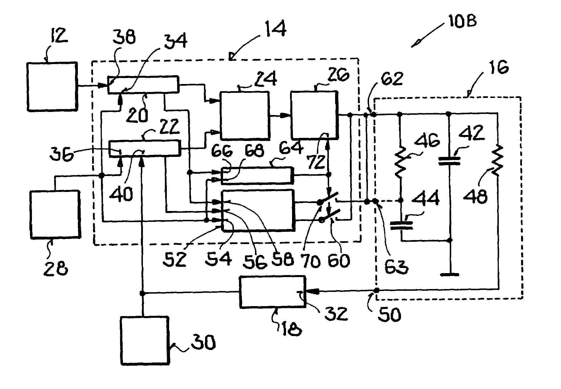
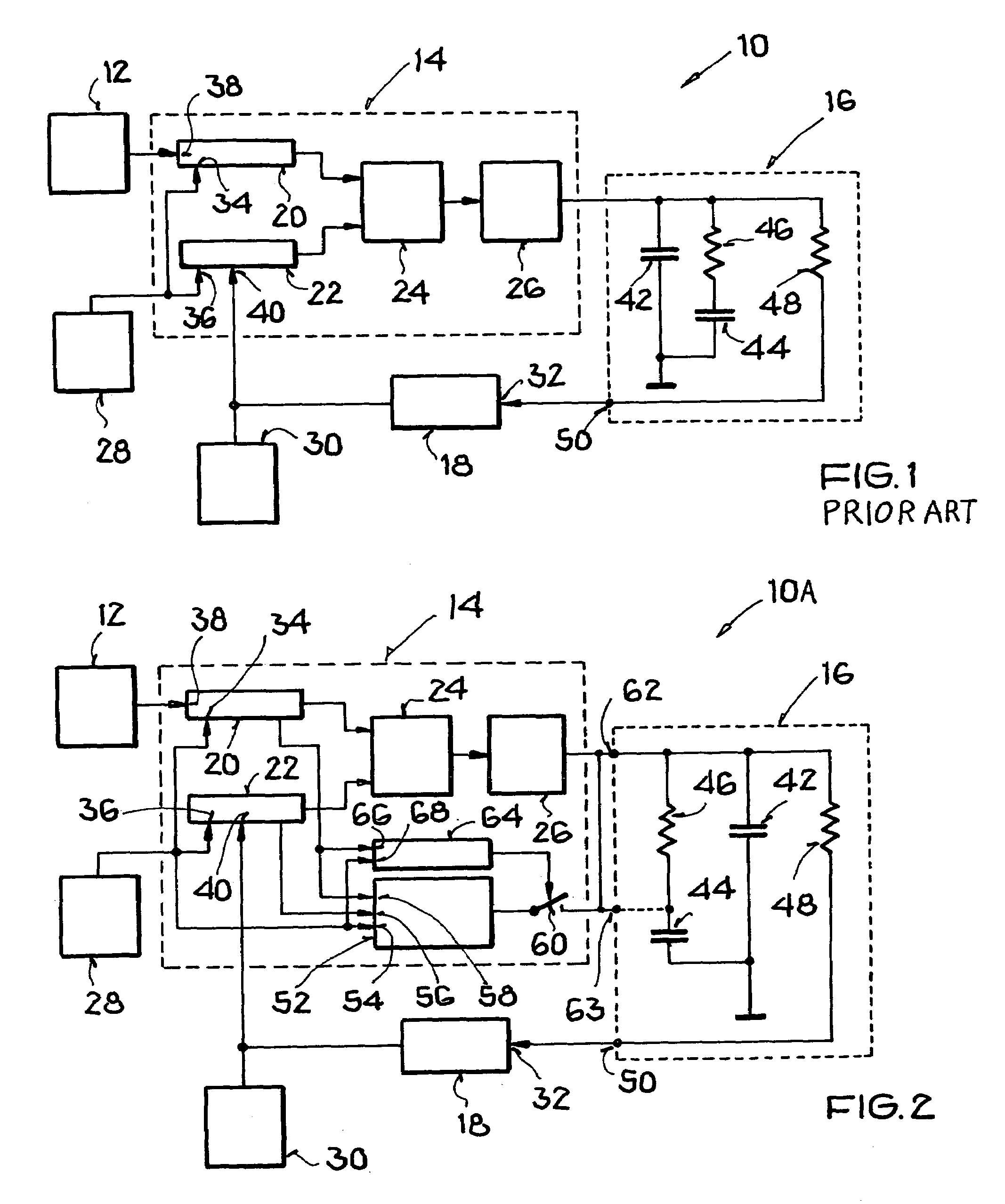
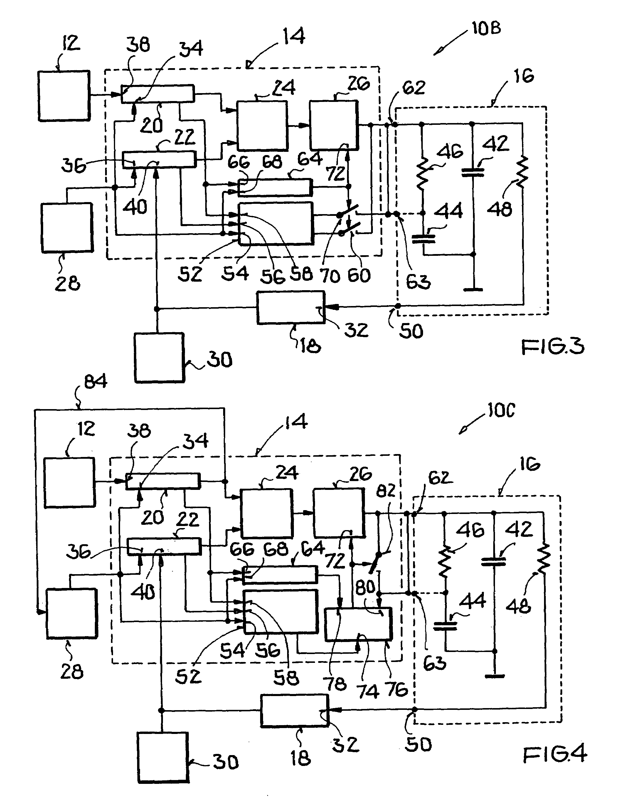
[0028]To provide a background understanding of the basic starting point of the present invention, FIG. 1 schematically shows a conventional circuit arrangement 10 for generating frequencies with a reference frequency generator or source 12, a phase locked loop (PLL) circuit 14, a loop filter 16, and a voltage controlled oscillator (VCO) 18. The PLL circuit 14 comprises a first frequency divider 20, a second frequency divider 22, a phase / frequency detector 24 and a charge pump 26. The PLL circuit 14 is controlled by a controller, and particularly an external controller 28. In the example according to FIG. 1, the output frequency generated by the VCO 18 is provided to a frequency synthesizer 30 of a transceiver, which is not shown further in FIG. 1.

[0029]For explaining the functioning or manner of operation of the conventional circuit arrangement 10 according to FIG. 1, this example is based on the assumption that the frequency synthesizer 30 of the transceiver requires a signal with ...


PUM


Abstract

A PLL circuit arrangement includes a first frequency divider connected to a reference frequency source, a second frequency divider connected to the output of an oscillator controlled by the output of a loop filter, a phase / frequency detector that detects phase / frequency differences between the two divider outputs, a charge pump between the detector and the loop filter, a controller providing a changeable divider ratio to the first and / or second frequency divider, and a regulating signal generator that changes the output voltage of the loop filter applied to the oscillator in a controlled manner in response to a change of the divider ratio. The signal generator preferably has inputs connected to outputs of the controller and the frequency dividers, and an output connected to the charge pump and / or the loop filter to accelerate the recharging thereof in response to a change of the divider ratio.

Description

PRIORITY CLAIM[0001]This application is based on and claims the priority under 35 U.S.C. §119 of German Patent Application 103 36 297.5, filed on Aug. 4, 2003, the entire disclosure of which is incorporated herein by reference.FIELD OF THE INVENTION[0002]The invention relates to a circuit arrangement and a method for generating frequencies with a phase regulating circuit, and particularly a phase locked loop including at least one frequency divider, a charge pump, a loop filter, and an oscillator arranged downstream of and controlled by the output of the loop filter.BACKGROUND INFORMATION[0003]The circuit and method of the above mentioned general type forming the field of this invention are known from the published European Patent application EP 0 993 122 A1. To generate a control voltage for controlling the voltage controlled oscillator (VCO), this European publication provides an adder circuit, which adds a predetermined frequency-dependent voltage to the output voltage of the loo...

Claims


Application Information

Patent Timeline
Patent Type & Authority Patents(United States)
IPC IPC(8): H03L7/00H03L7/089H03L7/093H03L7/10H03L7/183
CPCH03L7/0891H03L7/093H03L7/10H03L7/1072H03L7/183
Inventor HOFMANN, KARL
Owner ATMEL GERMANY
Why Eureka
Try Eureka