Stereoscopic image conversion panel and stereoscopic image display apparatus having the same

a technology of stereoscopic image and display apparatus, which is applied in the field of can solve the problems of relatively large thickness of the stereoscopic image conversion panel, and achieve the effects of reducing thickness, reducing thickness, and reducing the thickness of the stereoscopic image display apparatus

Active Publication Date: 2007-08-23
SAMSUNG DISPLAY CO LTD
View PDF3 Cites 48 Cited by
  • Summary
  • Abstract
  • Description
  • Claims
  • Application Information

AI Technical Summary

Benefits of technology

[0018]Therefore, since the stereoscopic image lens part includes the main lens and sub-lenses with reduced thickness compared to a conventional concave lens, the thickness of the stereoscopic image panel can be reduced, and thus the thickness of the stereoscopic image display apparatus can be reduced.

Problems solved by technology

However, since the stereoscopic image conversion panel includes concave lenses with a hemispheric shape, the thickness of the stereoscopic image conversion panel is relatively large.

Method used


Image

  • Stereoscopic image conversion panel and stereoscopic image display apparatus having the same
  • Stereoscopic image conversion panel and stereoscopic image display apparatus having the same
  • Stereoscopic image conversion panel and stereoscopic image display apparatus having the same

Examples


example embodiment 1

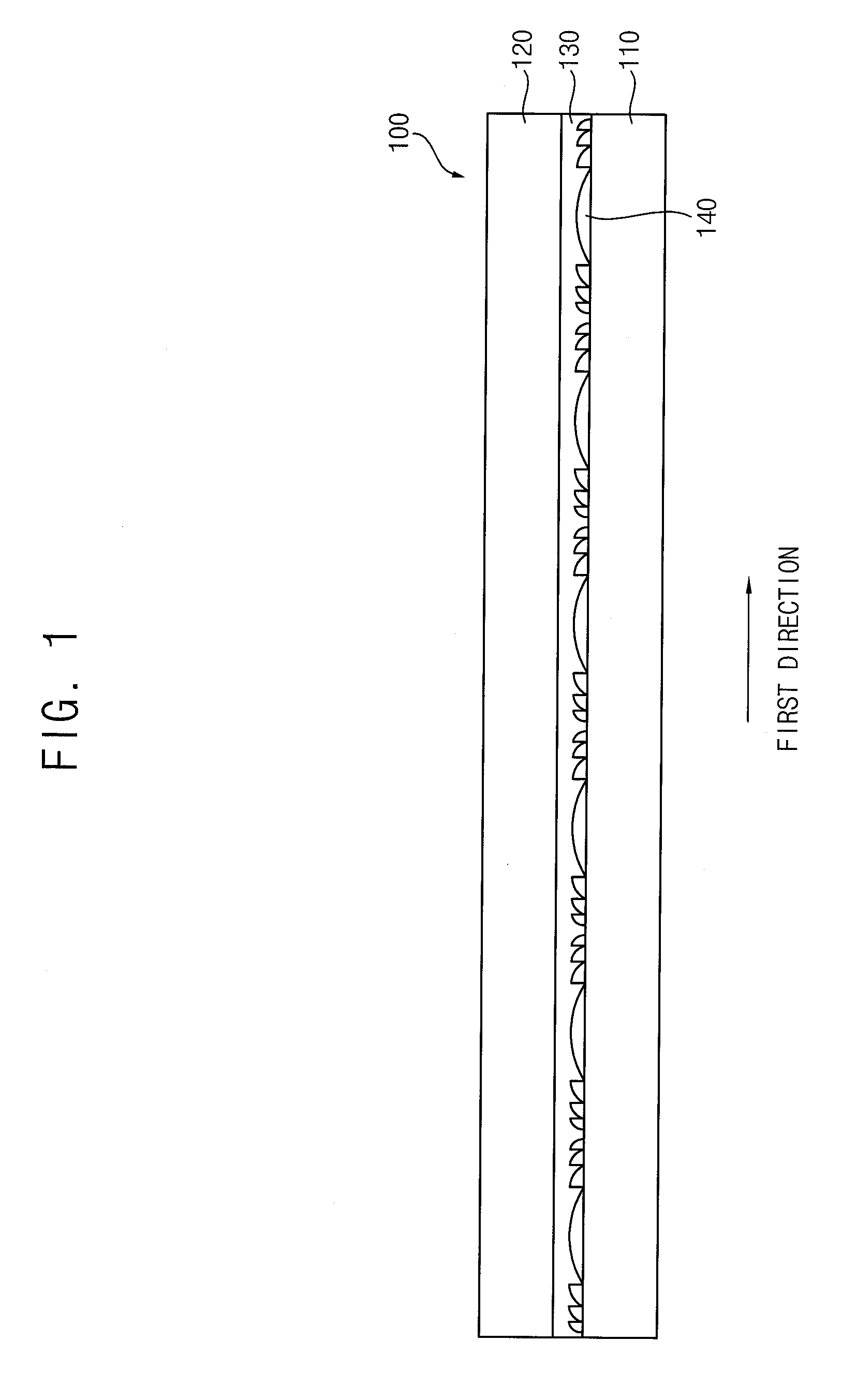
[0040]FIG. 1 is a cross-sectional view illustrating a stereoscopic image conversion panel according to a first example embodiment of the present invention.

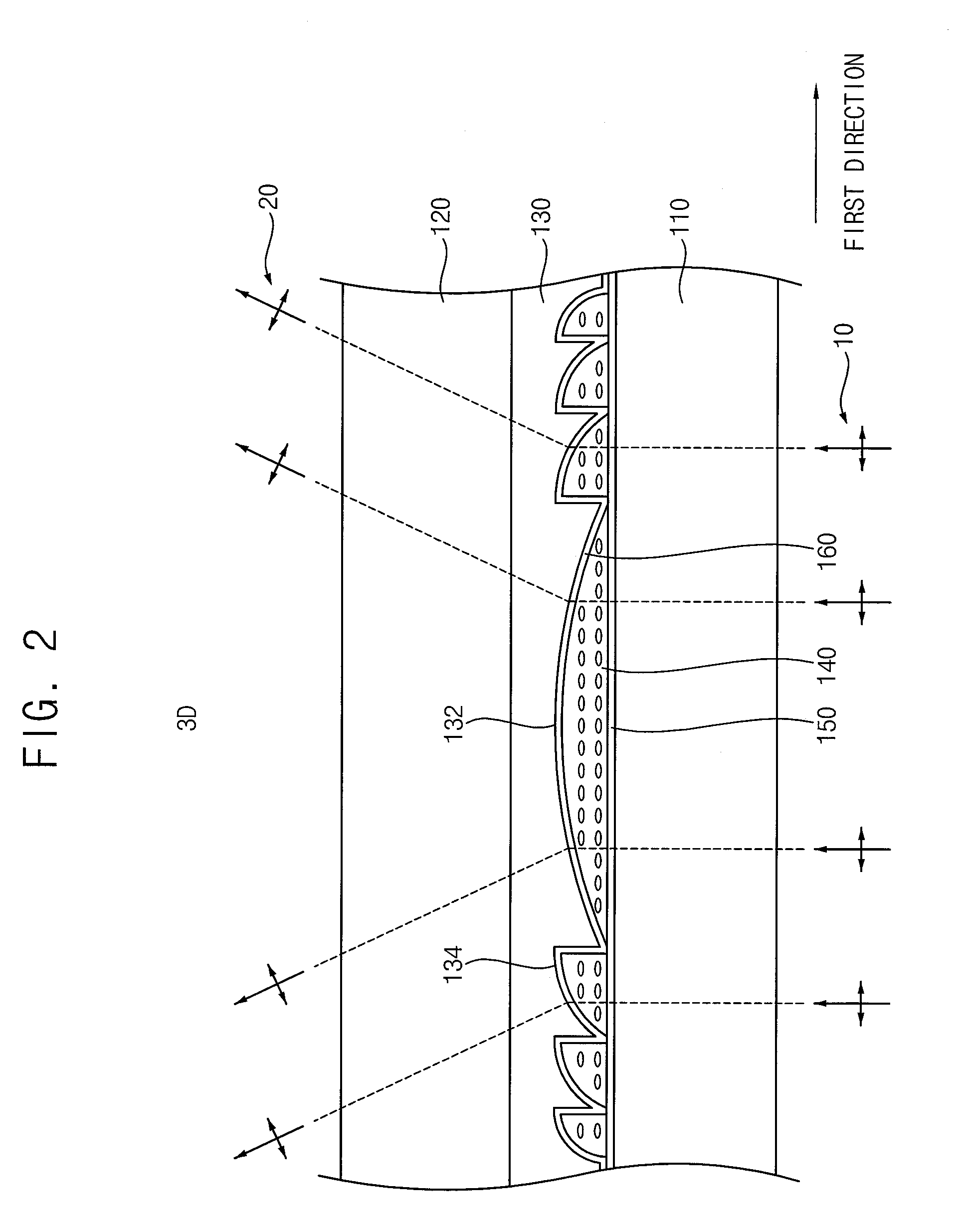
[0041]Referring to FIG. 1, the stereoscopic image conversion panel 100 according to the present example embodiment includes a first lens substrate 110, a second lens substrate 120, a stereoscopic image lens part 130 and a lens liquid crystal layer 140. The stereoscopic image conversion panel 100 converts light indicative of a flat image into light indicative of a stereoscopic image, and emits the stereoscopic image.

[0042]In the illustrated embodiment, the first and second lens substrates 110 and 120 have a plate-like shape, and may include, for example transparent glass, quartz, or a synthetic resin. The second lens substrate 120 faces the first lens substrate 110.

[0043]The stereoscopic image lens part 130 is disposed between the first and second lens substrates 110 and 120. The stereoscopic lens part 130 includes a plurality of u...

example embodiment 2

[0061]FIG. 4 is a cross-sectional view illustrating a stereoscopic image conversion panel according to a second example embodiment of the present invention, FIG. 5 is a partially enlarged sectional view illustrating the stereoscopic image conversion panel in FIG. 4, and FIG. 6 is a cross-sectional view illustrating an electric field generated in the stereoscopic image conversion panel based on an applied potential difference.

[0062]The stereoscopic image conversion panel of the present example embodiment is the same as in Example Embodiment 1 except for the addition of a first transparent electrode, a second electrode, and a power supply part. Thus, the same reference numerals will be used to refer to the same or like parts as those described in Example Embodiment 1, and further repetitive explanation concerning the above elements may be omitted

[0063]Referring to FIGS. 4, 5 and 6, the stereoscopic image conversion panel 100 according to the present example embodiment includes a first...

example embodiment 3

[0078]FIG. 7 is a cross-sectional view illustrating a stereoscopic image conversion panel according to a third example embodiment of the present invention, FIG. 8 is a partially enlarged sectional view illustrating the stereoscopic image conversion panel in FIG. 7, and FIG. 9 is a cross-sectional view illustrating an electric field generated in the stereoscopic image conversion panel in FIG. 8.

[0079]Referring to FIGS. 7, 8 and 9, the stereoscopic image conversion panel 200 according to the present example embodiment includes a first transparent substrate 210, a second transparent substrate 220, a transparent electrode 230, a stereoscopic image lens part 240, a lens liquid crystal layer 250, a first alignment film 260, a second alignment film 270, and a power supply part 280.

[0080]In the illustrated embodiment, the first and second transparent substrates 210 and 220 have a plate-like shape, include a transparent material, and are disposed to face one another.

[0081]The transparent ele...


PUM


Abstract

In a stereoscopic image conversion panel and a stereoscopic image display apparatus, the stereoscopic display panel includes a first lens substrate, a second lens substrate, a stereoscopic image lens part and a lens liquid crystal layer. The stereoscopic image lens part is disposed between the first and second substrates, and includes a main lens and sub-lenses with a concave shape. At least one sub-lens is disposed at opposite edge portions of the main lens. The lens liquid crystal layer is received by the main lens and the sub-lenses, is disposed between the first and second lens substrates, and includes liquid crystal molecules having an anisotropic refractive index. The lens liquid crystal layer refracts a polarized light at an interface between the lens liquid crystal layer and the stereoscopic lens part, to convert a flat image into a stereoscopic image. Therefore, the thickness of the stereoscopic image panel can be reduced.

Description

[0001]The present application claims priority under 35 USC § 119 to Korean Patent Application No. 2006-15527, filed on Feb. 17, 2006, the contents of which are herein incorporated by reference in their entirety.BACKGROUND OF THE INVENTION[0002]1. Field of the Invention[0003]The present invention relates to a stereoscopic image conversion panel and a stereoscopic image display apparatus having the stereoscopic image conversion panel.[0004]2. Description of the Related Art[0005]Recently, a stereoscopic image display apparatus capable of displaying a 3-D stereoscopic image has been developed, in response to increasing demand for 3-D stereoscopic images in applications such as games, movies, and so on.[0006]Generally, a stereoscopic image display apparatus displays two different 2-D flat images so that each of the user's eyes receives a slightly different view. As a result, the user perceives a 3-D stereoscopic image. For example, a user may view a pair of 2-D flat images, which the use...

Claims


Application Information

Patent Timeline
Patent Type & Authority Applications(United States)
IPC IPC(8): G02B27/22G02B30/25G02B30/29
CPCG02B27/2214G02F1/133526G02B27/26G02B30/25G02B30/29A01B1/022A01C5/02A01C7/02A01C3/06G02B30/27
Inventor YUN, HAE-YOUNGLIM, JAE-IKLEE
Owner SAMSUNG DISPLAY CO LTD
Why Eureka
Try Eureka