Adjustable optical mounting and method

a technology of optical mounting and adjustment, applied in the field of adjustable systems, can solve the problems of significantly time-consuming and complex process, extraordinarily burdensome system operation, and inability to adjust the system from the operating environment to the nominal ambient for each adjustment, so as to improve calibration quality, and minimize calibration cycles and delays.

Inactive Publication Date: 2007-08-23
RAYTHEON CO
View PDF9 Cites 13 Cited by
  • Summary
  • Abstract
  • Description
  • Claims
  • Application Information

AI Technical Summary

Benefits of technology

[0014] According to a still further aspect of the invention, a method of adjusting an optical system includes adjusting an optical mounting of the system while the system is operating in a controlled environment enclosure, thus minimizing calibration cycles and delays, and improving calibration quality.
[0015] According to another aspect of the invention, a method of adjusting an optical system includes the steps of: placing the optical system in a controlled environment enclosure; producing non-ambient conditions within the enclosure; and adjusting an optical mount of the optical system while the optical system is in the non-ambient conditions within the enclosure. This method minimizes calibration cycles and delays, and improves cali

Problems solved by technology

For high performance imagers, this process is complex and time consuming.
This is extraordinarily burdensome for systems that operate in cryogenic or vacuum environments, because human assemblers are not able to work in these environments.
Cycling the system from the operating environment to nominal ambient for each adjustment

Method used


Image

  • Adjustable optical mounting and method
  • Adjustable optical mounting and method
  • Adjustable optical mounting and method

Examples


Embodiment Construction

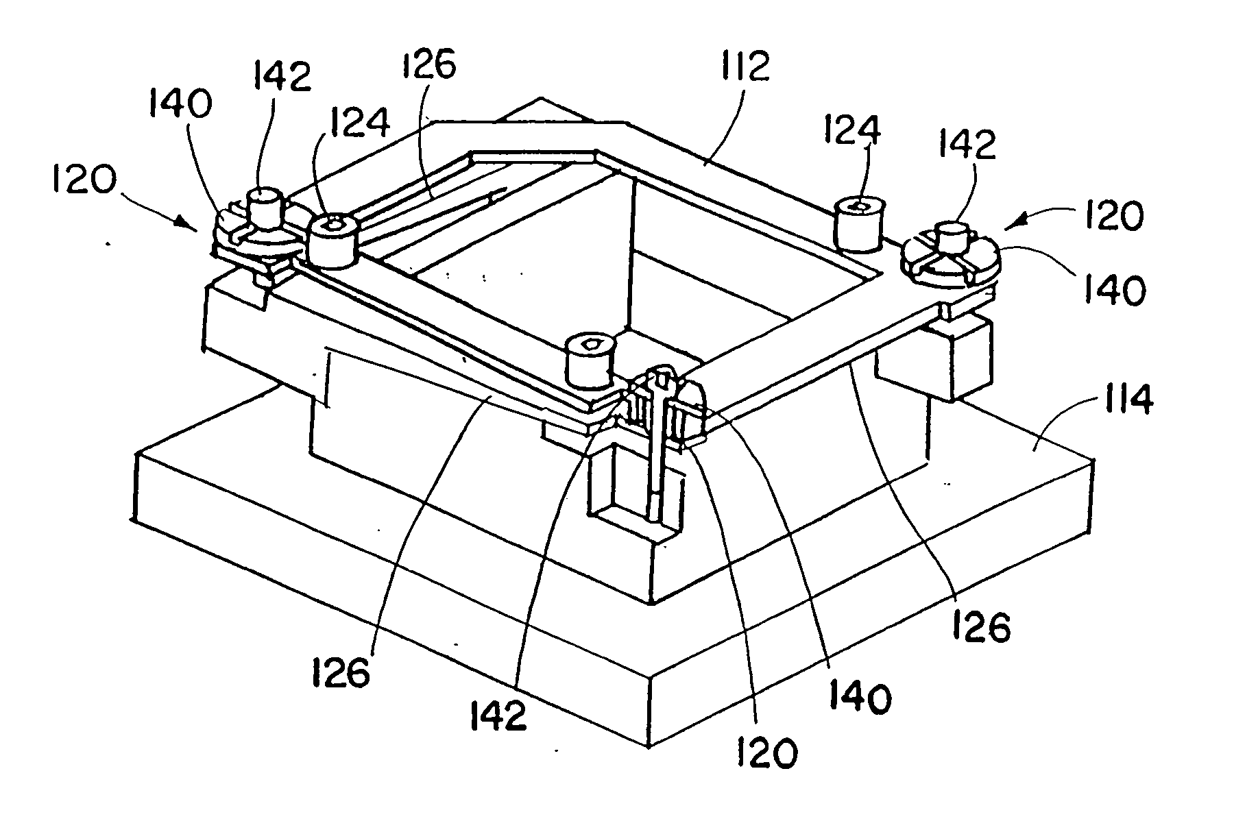
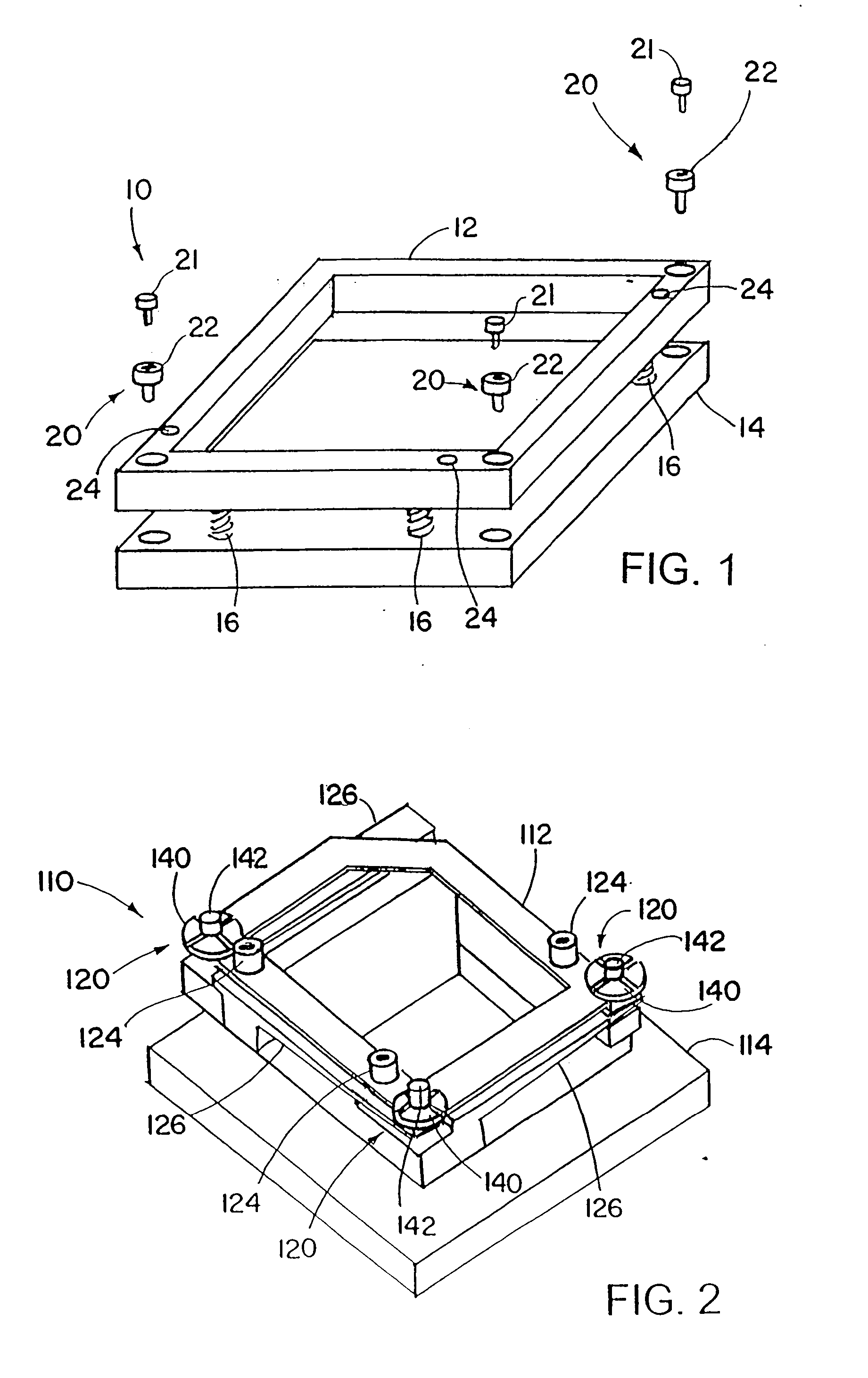
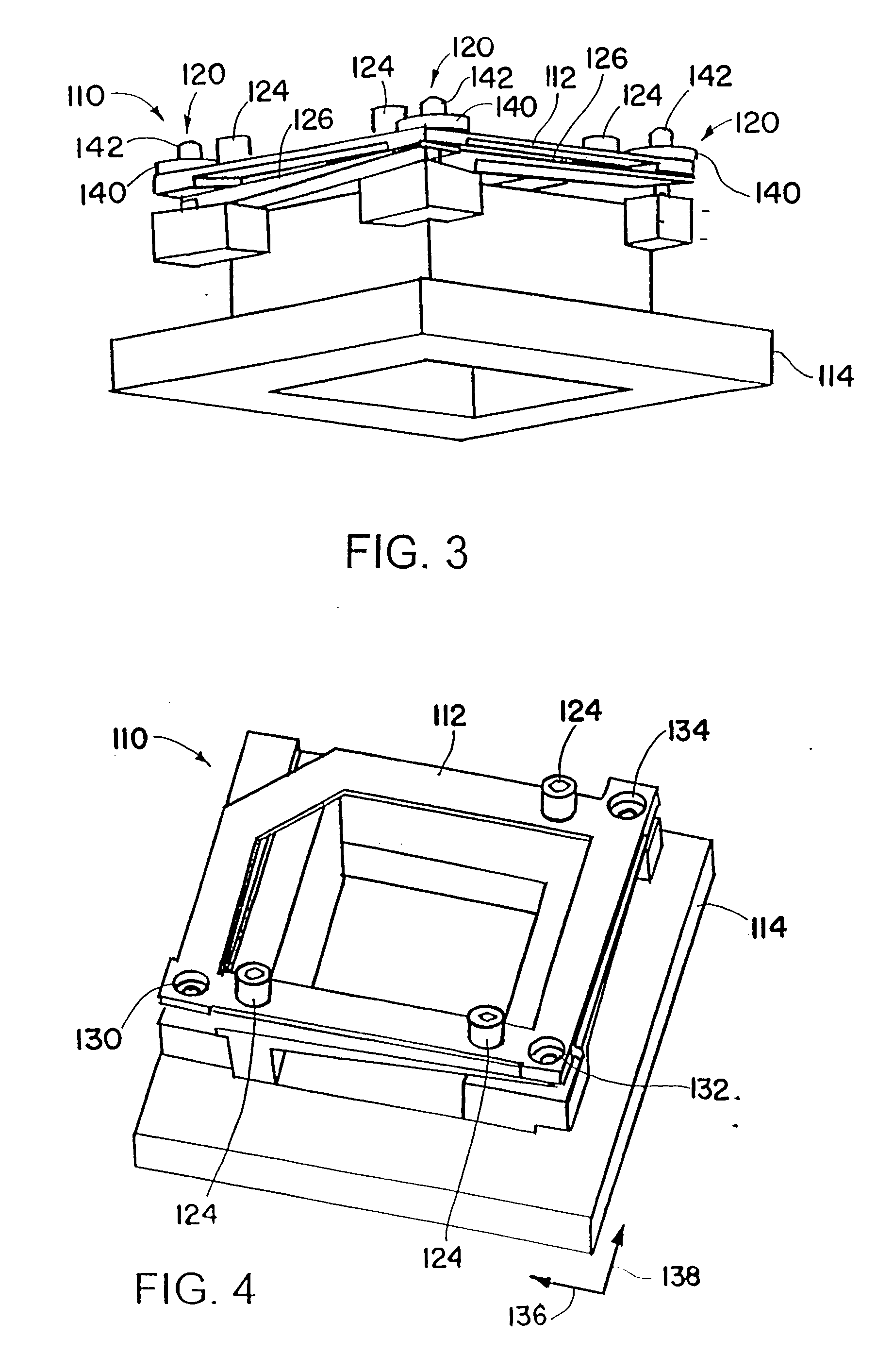
[0045] An adjustable optical mounting includes a mounting support or frame, and multiple adjusters to provide adjustment in at least four degrees of freedom of the support, relative to a base. The adjusters include cams with cam surfaces that bear against and engage slots in the support or frame, to translate the support in directions parallel to the base. In addition, threaded devices and resilient (compliant) devices such as springs are utilized to adjust the height of the support relative to the base, at multiple locations. The cams and the threaded devices of the adjusters may be independently adjusted to translate the support relative to the base, and / or to change the height and / or tilt angle of the support.

[0046] The adjustable optical mounting may be part of an optical system that is adjusted while in a controlled environment enclosure. The controlled environment enclosure may have a non-ambient temperature and / or pressure, for example being at a cryogenic temperature and / or...


PUM


Abstract

A method of adjusting an optical system includes placing the optical system in a controlled environment enclosure, and adjusting an optical mount of the optical system while the optical system is in the controlled environment enclosure.

Description

[0001] This application is a continuation in part of U.S. application Ser. No. 10 / 968,609, filed Oct. 19, 2004, and claims priority under 35 USC 119 of U.S. Provisional Patent Application No. 60 / 793,580, filed Apr. 19, 2006. Both of the above applications are hereby incorporated by reference in their entireties.BACKGROUND OF THE INVENTION [0002] 1. Technical Field [0003] The invention relates generally to adjustable systems for mounting devices, such as optical devices, and to methods for adjusting optical systems. [0004] 2. Background of the Related Art [0005] Position adjustment of optical imaging detectors in four or more degrees of freedom is currently accomplished by insertion of shims between an optical bench or mount and a detector assembly. For high performance imagers, this process is complex and time consuming. First a nominal shim is installed to position the detector in a nominally correct position. The entire sensor is assembled and extensive sensor characterization is ...

Claims


Application Information

Patent Timeline
IPC IPC(8): G02B7/02
CPCG02B7/004
Inventor THERIAULT, PHILIP C.LEE, ANTHONY O.ROTH, CHRISTOPHER A.
Owner RAYTHEON CO
Why Eureka
Try Eureka