Electrostatic ultrasonic transducer, method of manufacturing electrostatic ultrasonic transducer, ultrasonic speaker, method of reproducing sound signal, and super-directivity sound system, and display device

a technology of electrostatic ultrasonic transducers and ultrasonic speakers, which is applied in the direction of transducer diaphragms, electromechanical transducers, transducer types, etc., can solve the problems of deteriorating reproducing sound quality, high sound pressure, and extremely narrow frequency bands, so as to control the directivity of sound, the effect of easy control of the reproducing range of sound signals and increased membrane vibration amplitud

Inactive Publication Date: 2007-08-23
SEIKO EPSON CORP
View PDF7 Cites 46 Cited by
  • Summary
  • Abstract
  • Description
  • Claims
  • Application Information

AI Technical Summary

Benefits of technology

[0032]An advantage of some aspects of the invention is that it provides an electrostatic ultrasonic transducer, a method of manufacturing an electrostatic ultrasonic transducer, an ultrasonic speaker, a method of reproducing a sound signal, and super-directivity sound system, and a display device that are capable of improving an output sound pressure by increasing an effective membrane displacement of a vibration membrane and increasing an opening ratio of radiating holes (through-holes) radiating an ultrasonic wave.

Problems solved by technology

However, since the piezoelectric transducer utilizes a sharp resonance characteristic of an element, a high sound pressure is obtained, but a frequency band is extraordinarily narrow.
For this reason, a reproducible frequency band is narrow in an ultrasonic speaker that uses the piezoelectric transducer, and a reproducing sound quality becomes deteriorated, as compared with a loud speaker.
However, a maximum output sound pressure of the electrostatic ultrasonic transducer is slightly low, it is difficult to obtain an ultrasonic sound pressure necessary when obtaining a parametric array effect, and a ceramic piezoelectric element such as PZT or a high molecular piezoelectric element such as PVDF is used as an ultrasonic generator.
The mechanical processing is suitable in terms of processing precision, but since instead of the mechanical processing, the etching is used because of the problem of the cost.
For example, it is difficult to manufacture with the etching process, the electrodes that have the through-hole diameter of 0.75 mm and the thickness of 1.5 mm and satisfy the predetermined processing precision.
However, the radiating area of the sound wave is decreased, which lowers the radiating sound pressure.
However, since the electrostatic force becomes weaker, the membrane vibration amplitude is decreased, which lowers the radiating sound pressure.
However, in the structure according to the related art shown in FIG. 16B, the electrostatic force that is applied to the vibrating membrane is only applied to the outer circumferential portion of the vibration region, and it is difficult to generate the membrane vibration with high efficiency.

Method used


Image

  • Electrostatic ultrasonic transducer, method of manufacturing electrostatic ultrasonic transducer, ultrasonic speaker, method of reproducing sound signal, and super-directivity sound system, and display device
  • Electrostatic ultrasonic transducer, method of manufacturing electrostatic ultrasonic transducer, ultrasonic speaker, method of reproducing sound signal, and super-directivity sound system, and display device
  • Electrostatic ultrasonic transducer, method of manufacturing electrostatic ultrasonic transducer, ultrasonic speaker, method of reproducing sound signal, and super-directivity sound system, and display device

Examples


first embodiment

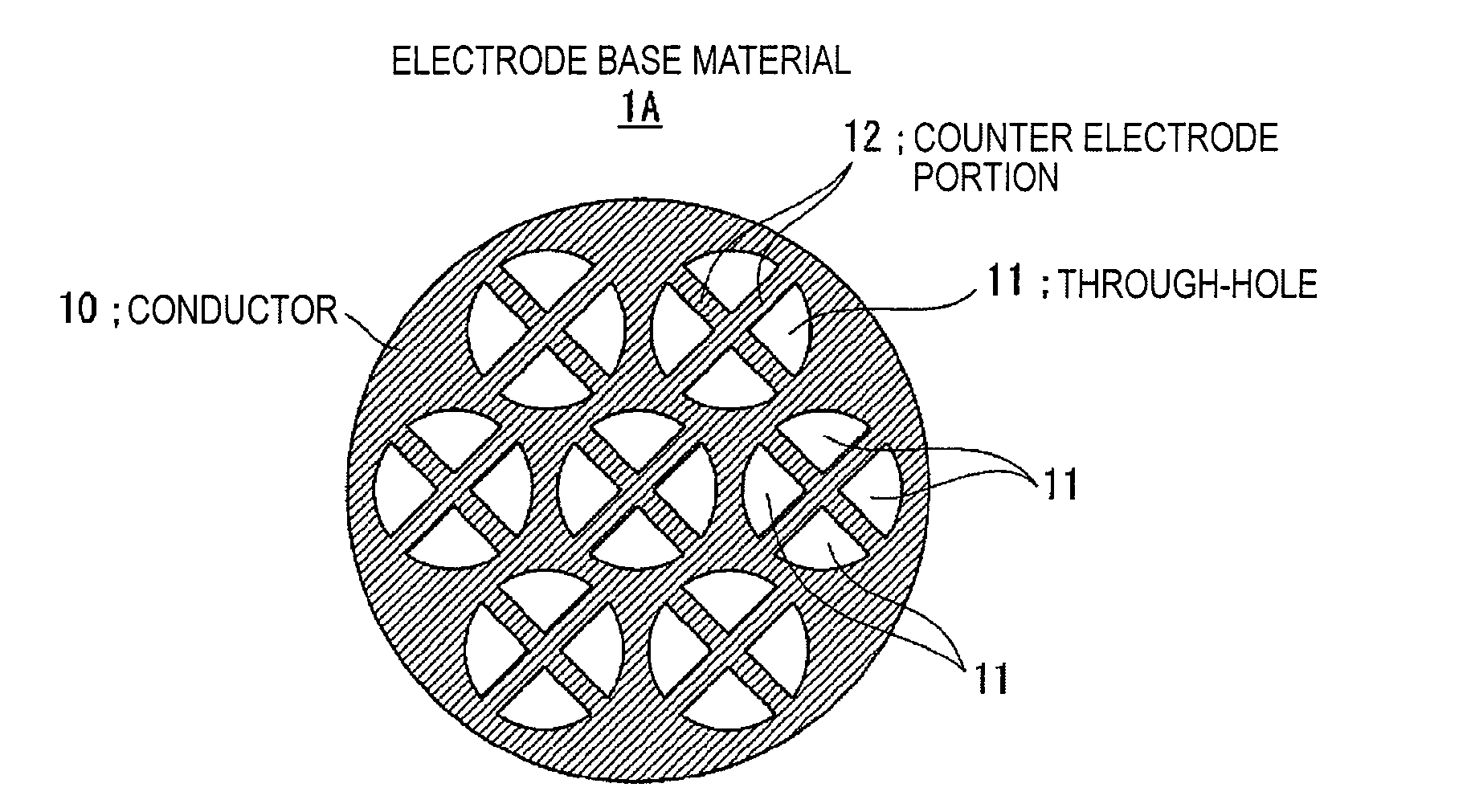
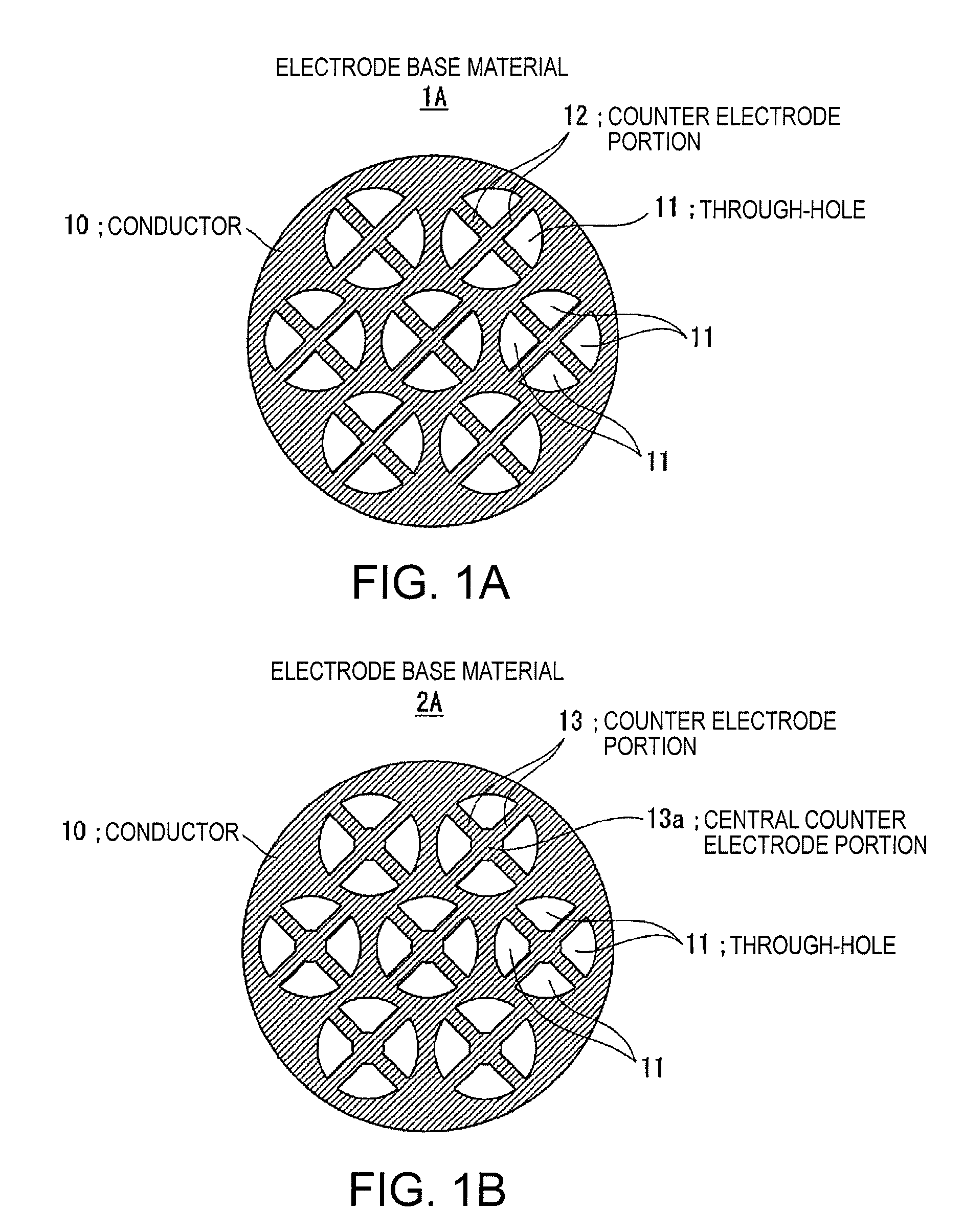
[0087]FIG. 1A is a diagram illustrating a counter electrode portion according to the invention, and illustrates an example of when counter electrode portions 12 having a cross-shaped bridge structure are disposed in through-holes 11 of a electrode base material 1A that is formed of a conductor 10. In this case, the bridge structure means a structure in which the counter electrode portions 12 build bridges between outer circumferential portions and inner portions of the through-holes 11, when the electrodes and the vibrating membrane are assembled so as to form the ultrasonic transducer, as apparent from FIG. 6 that shows an assembled state of the ultrasonic transducer.

second embodiment

[0088]FIG. 1B is a diagram illustrating a counter electrode portion according to the invention, and illustrates an example of when counter electrode portions 13, which form a cross-shaped bridge structure and have a structure where a central portion thereof (central counter electrode portion 13a) is wider than a bridge, are disposed in through-holes 11 of a electrode base material2A that is formed of a conductor 10.

third embodiment

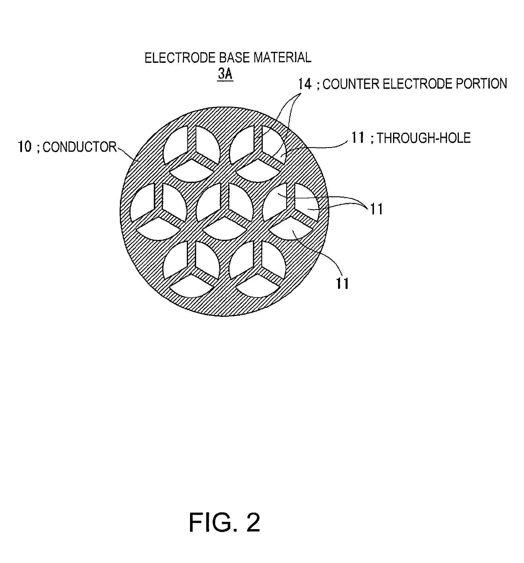
[0089]FIG. 2 is a diagram illustrating a counter electrode portion according to the invention, and illustrates an example of when counter electrode portions 14 each having a Y-shaped bridge structure are disposed in through-holes 11 of a electrode base material 3A.

[0090]Since it is very difficult to form the bridge structure through mechanical processing, it is preferable that an etching process be applied to a case where the bridge structure is formed. Further, there is a restriction in the relationships between the diameter of the through-hole formed by etching and the thickness of the base material to be processed. When forming a electrode that has the thickness larger than the diameter of the through-hole, a general method is used, as shown in FIGS. 18A to 18C.

[0091]FIGS. 18A to 18C show an example of a case where a through-hole has a circular shape. However, in order to form the counter electrode portion of the electrode according to the embodiment of the invention, the bridge ...


PUM


Abstract

An electrostatic ultrasonic transducer includes a first electrode that has through-holes, a second electrode that has through-holes, and a vibrating membrane that is disposed such that the through-holes of the first electrode and the through-holes of the second electrode form a pair, interposed between a pair of electrodes composed of the first electrode and the second electrode, and having a conductive layer applied with a direct current bias voltage. The first electrode and the second electrode each have counter electrode portions that are formed in the through-holes to face the vibrating membrane, and a modulated wave, which is obtained by modulating a carrier wave in an ultrasonic frequency band with a signal wave in an audible frequency band, is applied between the pair of electrodes.

Description

BACKGROUND[0001]1. Technical Field[0002]The present invention relates to an electrostatic ultrasonic transducer, a method of manufacturing an electrostatic ultrasonic transducer, an ultrasonic speaker, a method of reproducing a sound signal, an super-directivity sound system, and a display device that are capable of improving an output sound pressure by increasing an effective membrane displacement of a vibrating membrane and increasing an opening ratio of radiating holes (through-holes) radiating a sound wave.[0003]2. Related Art[0004]An ultrasonic transducer outputs a modulated wave obtained by modulating a carrier wave in an ultrasonic wave band with a sound signal in an audible band, and reproduces a sound having sharp directivity.[0005]FIGS. 15A and 15B are diagrams illustrating an example of a structure of an ultrasonic transducer according to the related art. Most of ultrasonic transducers according to the relate art are resonance-type ultrasonic transducers using piezoelectr...

Claims


Application Information

Patent Timeline
Patent Type & Authority Applications(United States)
IPC IPC(8): H04R25/00
CPCH04R19/013H04R7/045
Inventor SEKINO, HIROKAZUMATSUZAWA, KINYAKOJIMA, HIDEKI
Owner SEIKO EPSON CORP
Why Eureka
Try Eureka