Method of manufacturing toner and toner

a manufacturing method and technology of toner, applied in the field of toner manufacturing methods, can solve the problems of difficult to remove the surfactant after the manufacture of toner, difficult to reduce the diameter of toner particles, and difficult to reduce the size of toner particles, etc., to achieve excellent image reproducibility, high transfer efficiency of toner, and easy to cause toner

Inactive Publication Date: 2007-08-23
SHARP KK
View PDF9 Cites 11 Cited by
  • Summary
  • Abstract
  • Description
  • Claims
  • Application Information

AI Technical Summary

Benefits of technology

[0040]According to the invention, the toner obtained by the manufacturing method of the invention is provided. As described above, the toner has various advantages such that the toner is excellent in image reproducibility and hard to cause

Problems solved by technology

Regarding the enhancement in definition and resolution of the image, the reduction in diameter of toner particles is one of problems to be solved from the aspect of the developer.
However, resin represented by polyester, which is excellent in low-temperature fixing property and transparency and which is widely used as binder resin for toner, is hard to be granulated into fine particles.
Further, the use of a large amount of surfactant makes it difficul

Method used


Image

  • Method of manufacturing toner and toner

Examples


example 1

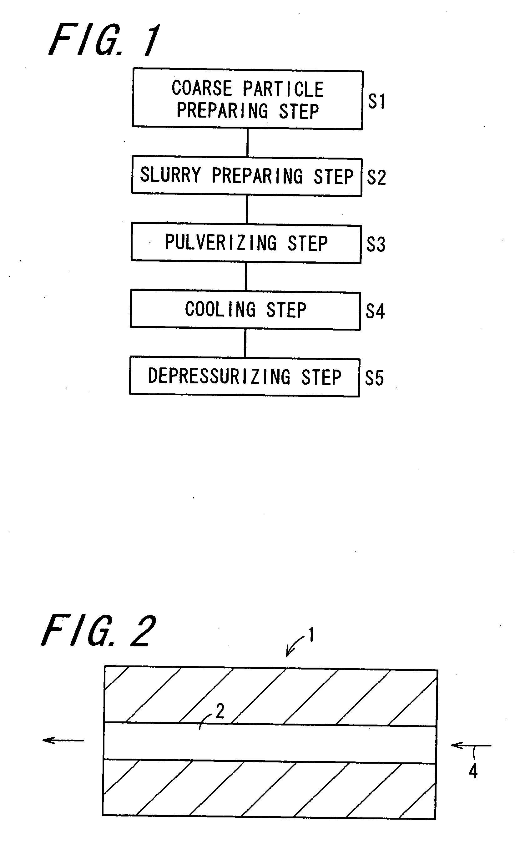
[0115]There were provided 92.5 parts by weight of polyester (having a weight-average molecular weight of 20,000, Mw / Mn of 24, and a softening temperature of 120° C.), 6 parts by weight of copper phthalocyanine blue, and 1.5 parts by weight of a charge control agent: TRH (trade name) manufactured by Hodogaya Chemical Co., Ltd. These constituent components were melt-kneaded by using a twin-screw extruder: PCM-30 (trade name) manufactured by Ikegai Co., Ltd. under cylinder setting temperature of 145° C. and barrel rotational speed of 300 rpm to prepare a melt-kneaded product of binder resin. The melt-kneaded product was then cooled down to a room temperature, thereafter being coarsely pulverized by a cutter mill: VM-16 (trade name) manufactured by Orient Co., Ltd. to prepare binder resin coarse particles having a particle diameter of 100 μm to 500 μm.

[0116]Next, 94 parts by weight of the melt-kneaded coarse particles obtained as described above and 20 parts by weight of an aqueous solu...

example 2

[0119]There were provided 92.5 parts by weight of polyester (having a weight-average molecular weight of 20,000, Mw / Mn of 24, and a softening temperature of 120° C.), 5 parts by weight of polyester wax (serving as a releasing agent and having a melting temperature of 85° C.), 6 parts by weight of copper phthalocyanine blue, and 1.5 parts by weight of a charge control agent: TRH (trade name) manufactured by Hodogaya Chemical Co., Ltd. These constituent components were melt-kneaded by using a twin-screw extruder: PCM-30 (trade name) manufactured by Ikegai Co., Ltd. under cylinder setting temperature of 145° C. and barrel rotational speed of 300 rpm to prepare a melt-kneaded product of binder resin. The melt-kneaded product was then cooled down to a room temperature, thereafter being coarsely pulverized by a cutter mill: VM-16 (trade name) manufactured by Orient Co., Ltd. to prepare binder resin coarse particles. The following operation was carried out as in the case of Example 1, thus...


PUM

PropertyMeasurementUnit
Temperatureaaaaaaaaaa
Pressureaaaaaaaaaa

Abstract

In a method of manufacturing a toner in which toner particles are obtained by mixing resin particles and at least a colorant with each other to be coagulated, and heating an obtained coagulated product, binder resin is granulated into fine particles by a granulating method including a coarse particle preparing step, a slurry preparing step, a pulverizing step, a cooling step, and a depressurizing step. Slurry containing coarse particles of binder resin obtained by way of the coarse particle preparing step and the slurry preparing step is made to pass under heat and pressure through a pressure-resistant nozzle whereby the coarse particles of binder resin are pulverized into resin particles. By providing the cooling step and the depressurizing step immediately after the pulverizing step, the resin particles are prevented from coarsening.

Description

CROSS-REFERENCE TO RELATED APPLICATION[0001]This application claims priority to Japanese Patent Application No. JP 2006-43072, which was filed on Feb. 20, 2006, the contents of which, are incorporated herein by reference, in their entirety.BACKGROUND OF THE INVENTION[0002]1. Field of the Invention[0003]The present invention relates to a method of manufacturing a toner, as well as a toner.[0004]2. Description of the Related Art[0005]An electrophotographic image forming apparatus comprises an image forming process mechanism including: a photoreceptor; a charging section for charging a photoreceptor surface; an exposing section for irradiating with signal light the photoreceptor surface being charged, to form thereon an electrostatic latent image corresponding to image information; a developing section for supplying a toner contained in a developer to the electrostatic latent image formed on the photoreceptor surface, to form thereon a toner image; a transfer section provided with a tr...

Claims


Application Information

Patent Timeline
IPC IPC(8): G03G9/08
CPCG03G9/0804G03G9/08755G03G9/0817G03G9/0815
Inventor MATSUMOTO, KATSURUSHIBAI, YASUHIRO
Owner SHARP KK
Why Eureka
Try Eureka