Dental guard for airway intubation

Inactive Publication Date: 2007-08-23
LANE EDWARD D
View PDF13 Cites 16 Cited by
  • Summary
  • Abstract
  • Description
  • Claims
  • Application Information

AI Technical Summary

Benefits of technology

[0021] The present invention is directed to a dental guard that is designed to reduce the risk of dental injuries in the course of endotracheal intubatio

Problems solved by technology

Use of a gentle technique for inserting the laryngoscope, may lessen, but cannot totally remove the possibility of intubation trauma.
However, poor dentition or suboptimal anatomy of the teeth, jaw, neck, or throat may leave the maxillary incisors at particularly significant risk during intubation by even the most experienced of technicians.
During emergency response situations, either in the field by paramedics or in the hospital emergency rooms for example, such gentle techniques are often not realized.
Because the laryngoscope is necessarily formed of a hard, inflexible material, dental damage is a potential result of such intubation procedures.
The risk of such dental injury is typically aggravated when the upper teeth are used as a fulcrum during insertion procedures, as they commonly are.
The prior art teaches that other protective shields have limited advantage in preventing dental injuries during intubation.
The shields cover the maxillary incisors, yet provide only limited protection for the teeth.
Such shields are prone to displacement by either the laryngoscope blade or other instrumentation.
Furthermore, existing shields are relatively difficult to use, requiring multiple operator steps to secure the shields for use.
The multiple steps required to secure existing shields may discourage their use by significantly increasing the time and effort required to achieve the desire

Method used


Image

  • Dental guard for airway intubation
  • Dental guard for airway intubation
  • Dental guard for airway intubation

Examples


Example

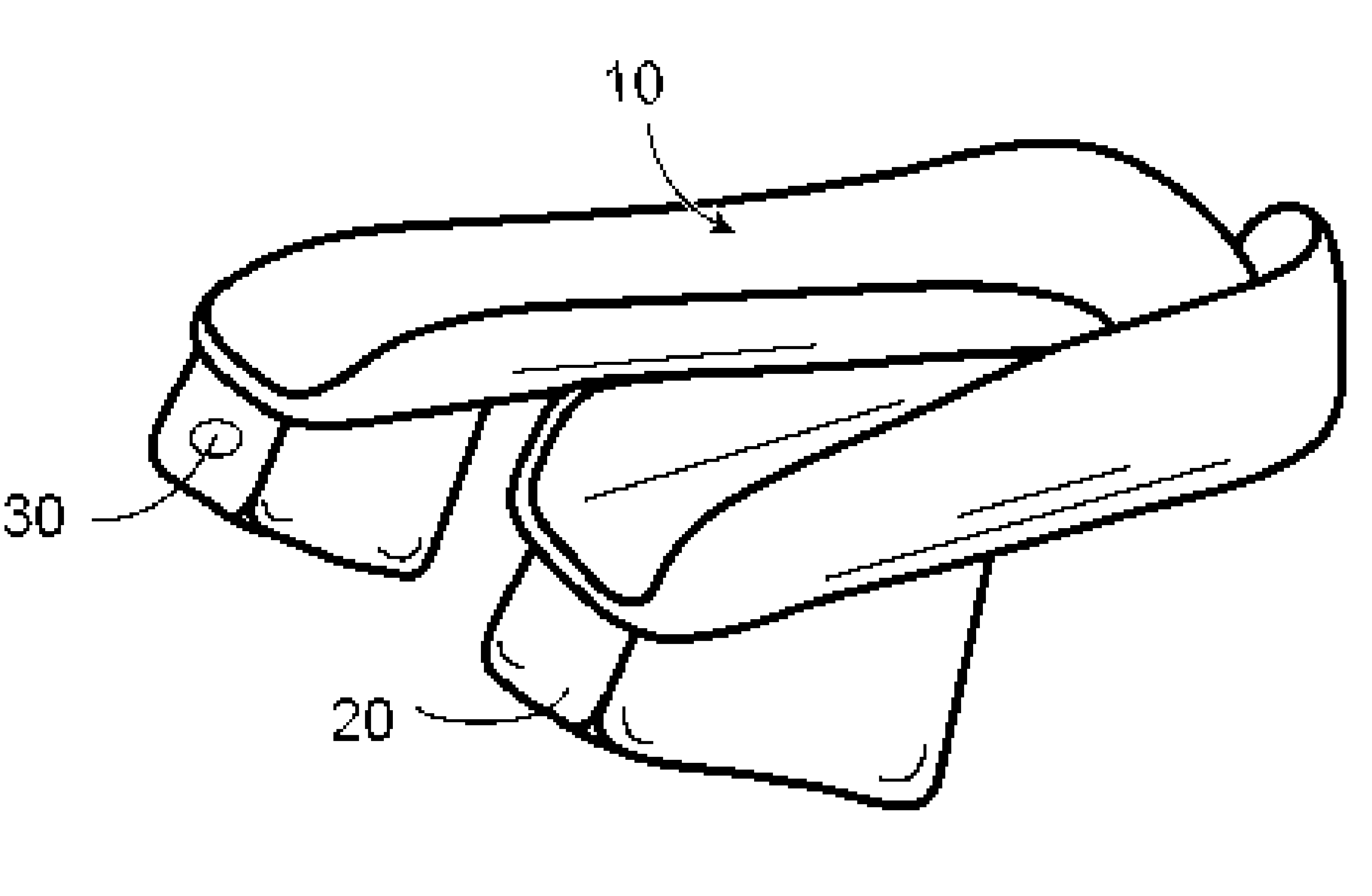
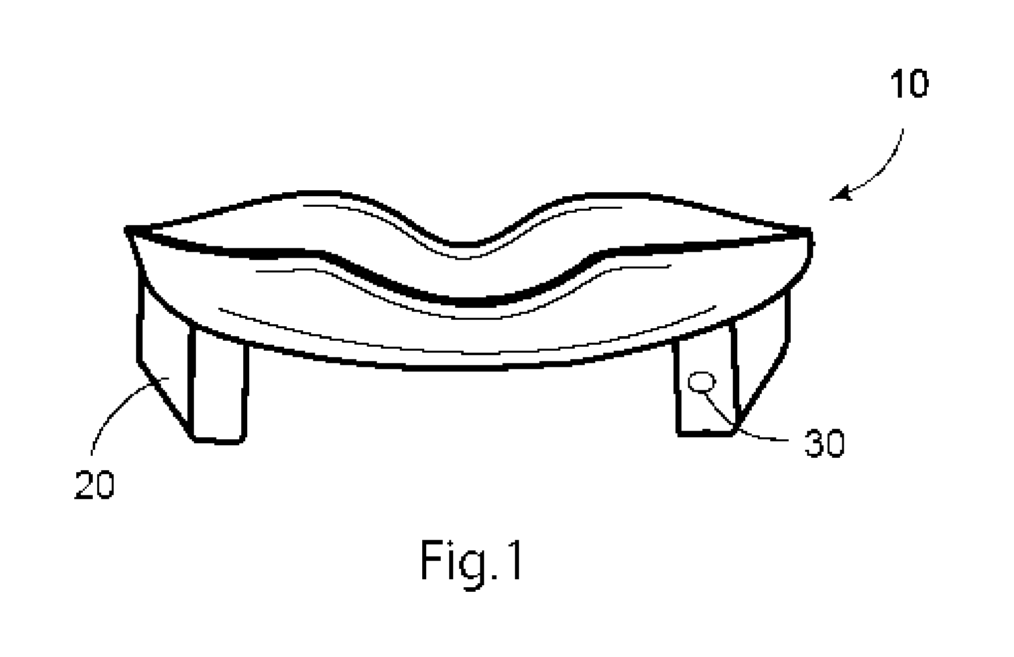
[0038] An overview of a preferred embodiment of the present invention is illustrated in FIG. 1. The inventive dental guard comprises a mouthguard 10 that covers and grips the incisors and other maxillary teeth as far back as the molars, and also comprises trapezoidal blocks or wedges 20 attached or fused to the mouthguard. The location of an optional light emitting diode LED or other light source 30 is included in the left wedge.

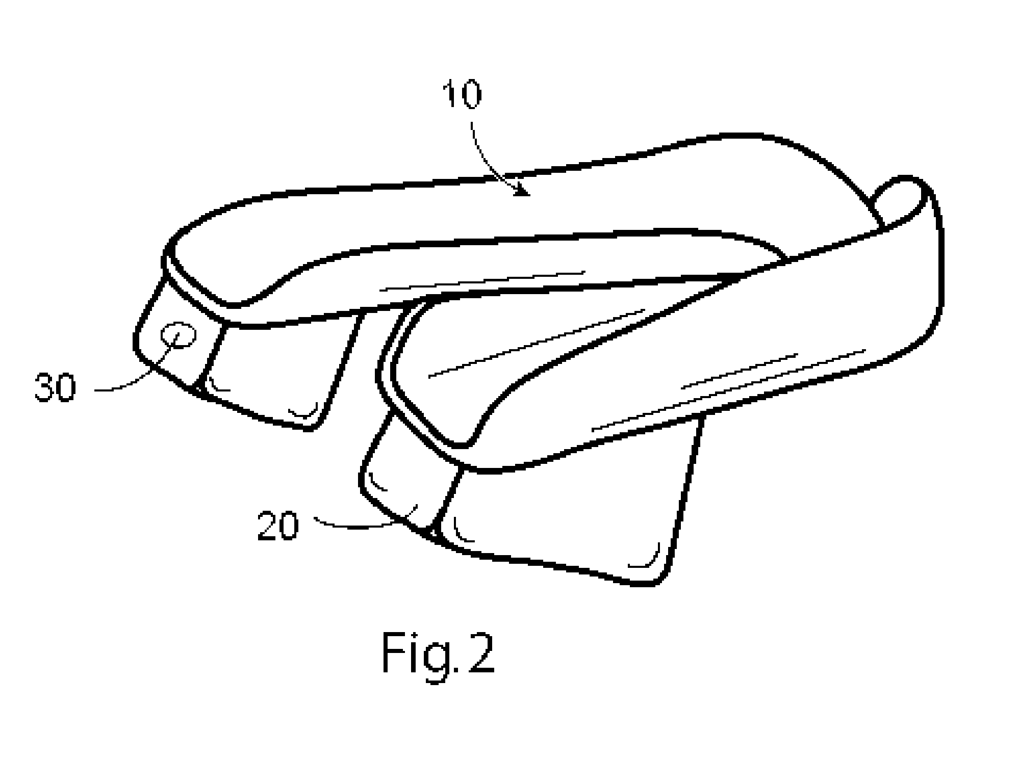
[0039]FIG. 2 provides an alternative view of the dental guard from the right posterior perspective, illustrating the trough nature of the mouthguard 10, and further illustrating the location of the trapezoidal blocks 20 with respect to the guard. The trapezoidal block on the left side in a preferred embodiment may include a channel or interior cavity to contain a miniature light 30 such as a conventional light or an LED, and its power source 40, typically a battery. This light is directed to the back of the mouth, to provide additional lighting for the bene...


PUM


Abstract

The present invention relates to the field of medical devices used in orotracheal intubation. The insertion and manipulation of laryngoscopes used by medical personnel may occasionally cause damage or breakage of incisors or other maxillary teeth. The present invention provides a device useful for the prevention of tooth damage occurring with common laryngoscopes and other airway intubation systems. The device comprises an upper mouthguard for the maxillary teeth attached to blocks or wedges for keeping the jaw open. Optionally, a light such as an LED may be incorporated in one of the blocks to facilitate the intubation procedure. The invention is placed into the subject's mouth, and then intubation using a laryngoscope may be safely performed. Once intubation has been accomplished, and the laryngoscope has been removed, the dental guard of this invention may be retained in the patient's jaw as a bite block, or removed, or replaced with another type of bite block.

Description

CROSS-REFERENCE TO RELATED APPLICATIONS [0001] Not Applicable. STATEMENT REGARDING FEDERALLY SPONSORED RESEARCH OR DEVELOPMENT [0002] Not Applicable. REFERENCE TO SEQUENCE LISTING, A TABLE, OR A COMPUTER PROGRAM LISTING COMPACT DISC APPENDIX [0003] Not Applicable. FIELD OF THE INVENTION [0004] The present invention relates to the field of medical devices used in the procedures of orotracheal intubation. More particularly, the present invention relates to a dental guard which is designed to distribute and dissipate both direct pressure and shear forces on the maxillary incisor teeth when the laryngoscope is placed in a patient's mouth and manipulated during intubation. BACKGROUND OF THE INVENTION [0005] Endotracheal intubation procedures are commonly employed to secure a controlled airway and to deliver oxygen or anesthetic gases into the lungs of patients. These procedures are often performed by emergency response technicians rendering aid to victims in the field, or sometimes while...

Claims


Application Information

Patent Timeline
IPC IPC(8): A61B1/267
CPCA61B1/00154A61B1/018A61B1/267A61M16/0488A61B17/24A61B2019/481A61B2019/521A61B5/0088A61B2090/309A61B2090/08021A61M16/0493
Inventor LANE, EDWARD D.
Owner LANE EDWARD D
Why Eureka
Try Eureka