Cutting balloon catheter assembly

a technology of cutting balloon and catheter, which is applied in the field of medical devices, can solve the problems of narrow passageway, easy buildup of plaque in the arteries,

Inactive Publication Date: 2007-08-23
TWINCATH
View PDF47 Cites 59 Cited by
  • Summary
  • Abstract
  • Description
  • Claims
  • Application Information

AI Technical Summary

Problems solved by technology

Generally, arteries are susceptible to the buildup of plaque.
Additionally, when there i...

Method used


Image

  • Cutting balloon catheter assembly
  • Cutting balloon catheter assembly
  • Cutting balloon catheter assembly

Examples


Embodiment Construction

[0017] In the drawings, like numerals indicate like elements throughout. Certain terminology is used herein for convenience only and is not to be taken as a limitation on the present invention. The words “proximal” and “distal” refer to directions away from and closer to, respectively, the tip of the double lumen catheter assembly that makes up a portion of the cutting balloon assembly according to the present invention. The terminology includes the words above specifically mentioned, derivatives thereof, and words of similar import. The following describes preferred embodiments of the invention. However, it should be understood based on this disclosure, that the invention is not limited by the preferred embodiments described herein.

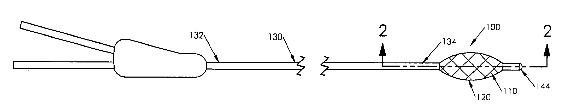
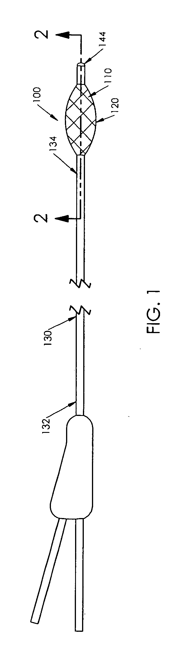
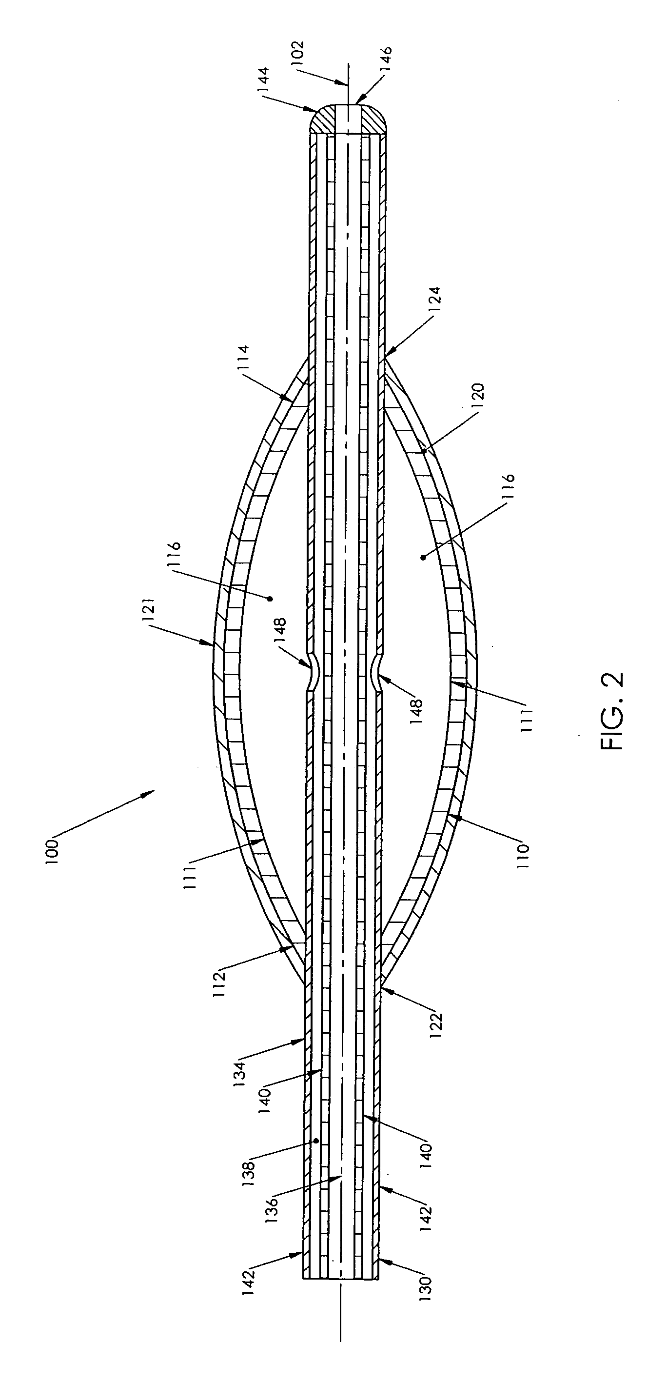
[0018] Referring to FIGS. 1 and 2, a first preferred embodiment of a cutting balloon catheter assembly 100 according to the present invention is shown. Balloon assembly 100 is used to expand a patient's blood vessel by cutting blockages within the vesse...


PUM


Abstract

A cutting balloon catheter assembly (100) including a dual lumen catheter (130) having a distal end (134), an inflation/deflation lumen (138) and a second or guidewire lumen (136). The assembly further includes an inflatable balloon (110) having an interior cavity (116) and an expandable covering (120) disposed about the balloon wherein the covering has an array of cutting edges. In the assembly, the balloon (110) is fixedly connected to the distal end (134) of the catheter and the interior cavity (116) of the balloon (110) is in fluid communication with the first lumen (138) of the catheter (130). A method of removing obstructions (149) from vessel walls (154) using the present invention is also disclosed wherein the cutting edges abrade the stenoses, plaque or lesions along the vessel walls, when the catheter assembly is reciprocally moved longitudinally or rotationally after inflation of the balloon.

Description

CROSS-REFERENCE TO RELATED APPLICATION [0001] This application claims priority from U. S. Provisional Patent Application Ser. No. 60 / 751,865 filed Dec. 20, 2005.FIELD OF THE INVENTION [0002] The present invention relates to medical devices and more particularly to a cutting balloon device for expanding passageways in the venous system. BACKGROUND OF THE INVENTION [0003] One of the most common heart diseases in industrialized countries is atherosclerotic cardiovascular disease, caused by the buildup of plaque or stenoses in the blood vessels. This affliction affects not only veins or arteries, but also dialysis access systems such as fistulas or grafts. Generally, arteries are susceptible to the buildup of plaque. The venous system, however, has lesions that are generally fibrous in nature, usually in the form of scar tissue or venous valvular rings. Additionally, when there is long term placement of a fistula or graft, there is a tendency for the passageway to narrow. The venous ana...

Claims


Application Information

Patent Timeline
IPC IPC(8): A61M29/00
CPCA61B17/320725A61B2017/22061A61B2017/00557
Inventor SCHON, DONALDMISHLER, RICKSCHWEIKERT, TIMOTHY
Owner TWINCATH
Why Eureka
Try Eureka