
Electrospray coating of objects

a technology of electrostatic spraying and objects, applied in the direction of electrostatic spraying apparatus, spray discharge apparatus, chemical/physical processes, etc., can solve the problems of avoiding the need for balloon delivery devices, difficult to describe each and every stent structure or related materials, and difficult to achieve uniform coatings. achieve the effect of stable cone-j

Inactive Publication Date: 2007-08-30
RGT UNIV OF MINNESOTA +1
View PDF99 Cites 53 Cited by
  • Summary
  • Abstract
  • Description
  • Claims
  • Application Information

AI Technical Summary

Benefits of technology

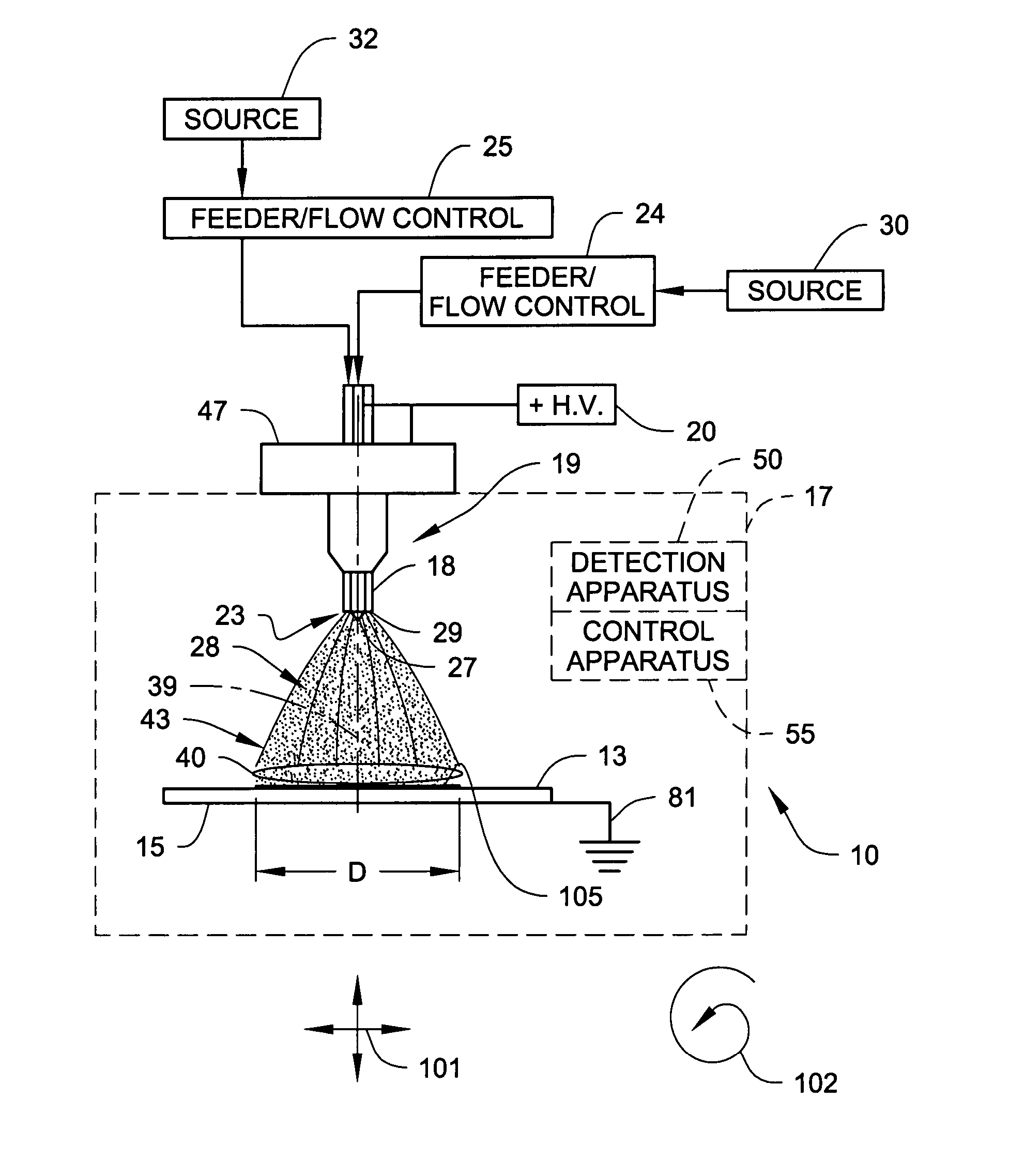
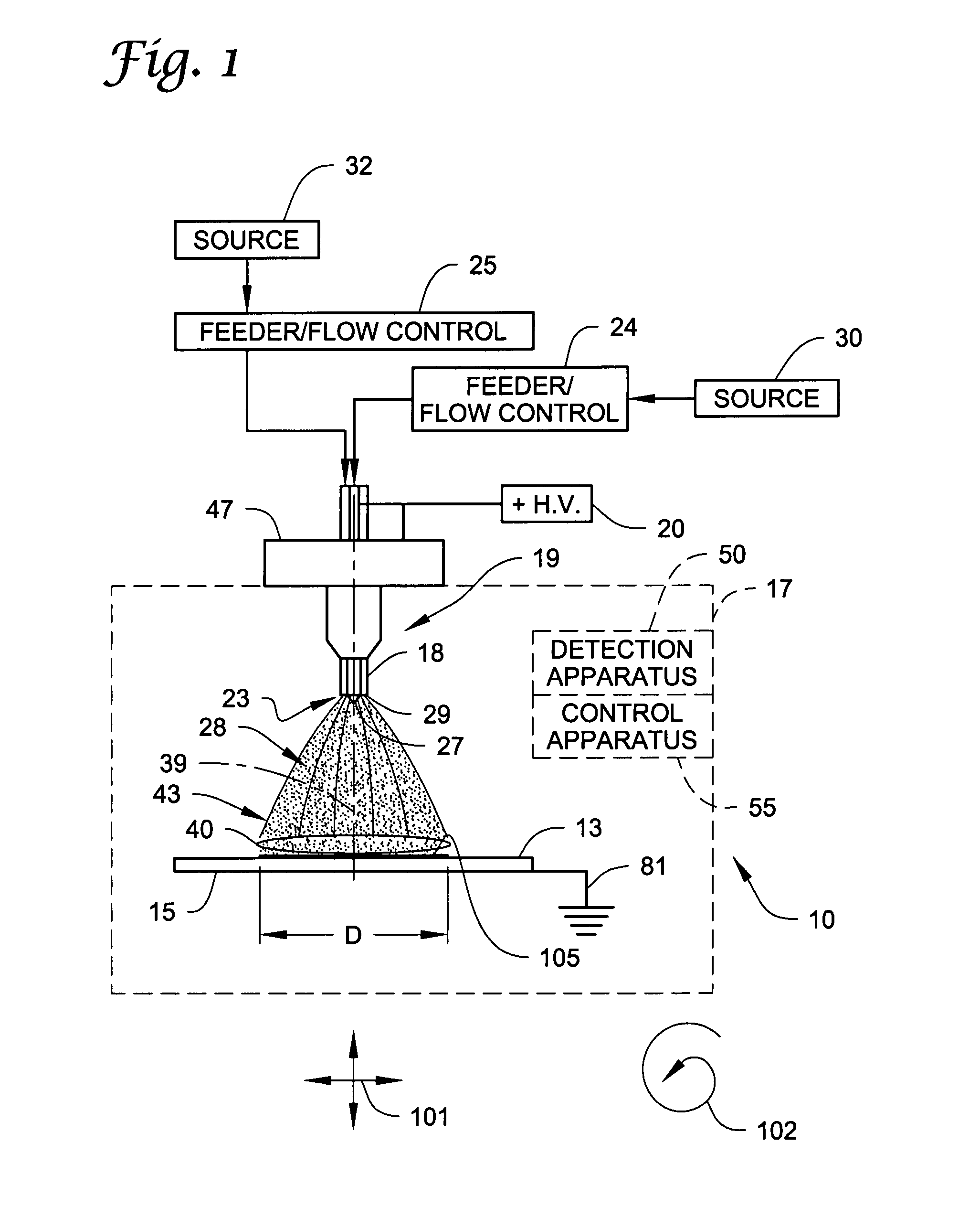
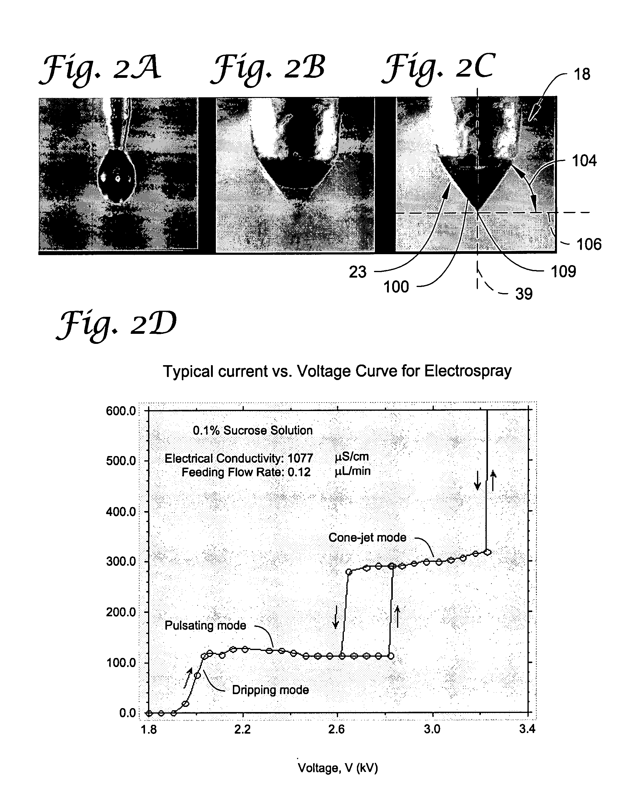
[0016] Yet another method of coating at least a portion of an object includes providing an object in a defined volume (e.g., the object includes at least one surface) and providing one or more nozzle structures (e.g., each nozzle structure includes one or more openings terminating at a dispensing end of each nozzle structure). One or more flows of liquid compositions are provided to the openings and a plurality of charged coating particles are generated forward of the dispensing end of each nozzle structure to apply a coating to the at least one surface of the object. Generating the plurality of charged coating particles includes dispensing a stream of a plurality of microdroplets having an electrical charge associated therewith from the dispensing end of each nozzle structure by creating a cone-jet from the one or more flows at the dispensing end of each nozzle using a nonuniform electrical field between the dispensing end of each nozzle structure and the object. The plurality of charged coating particles having a nominal diameter of less than 10 micrometers are formed as the microdroplets evaporate. Using the nonuniform electrical field between the dispensing end of each nozzle structure and the object to generate the plurality of charged coating particles includes applying an electrical potential difference between the dispensing end of each nozzle structure and the object being coated so as to create the cone-jet from the one or more flows at the dispensing end of each nozzle structure. The method further includes adjusting the electrical potential difference between the dispensing end of each nozzle structure and the object being coated as the thickness of the coating increases so as to maintain a stable cone-jet at the dispensing end of each nozzle structure. Systems for carrying out this method are also provided.
[0017] Still another method of coating at least a portion of an object includes providing an object in a defined volume (e.g., the object includes at least one surface) and providing one or more nozzle structures. Each nozzle structure includes one or more openings terminating at a dispensing end of each nozzle structure. One or more flows of liquid compositions are provided to the openings and a plurality of charged coating particles are generated forward of the dispensing end of each nozzle structure to apply a coating to the at least one surface of the object. Generating the plurality of charged coating particles includes dispensing a stream of a plurality of microdroplets having an electrical charge associated therewith from the dispensing end of each nozzle structure by creating a cone-jet from the one or more flows at the dispensing end of each nozzle using a nonuniform electrical field between the dispensing end of each nozzle structure and the object. The plurality of charged coating particles having a nominal diameter of less than 10 micrometers are formed as the microdroplets evaporate. The method further includes detecting at least one characteristic associated with the cone-jet, determining the stability of the cone-jet based on the at least one characteristic, and adjusting one or more process parameters to maintain a stable cone-jet.
[0018] In one or more embodiments of the method, detecting at least one characteristi

Problems solved by technology

Further, for example, the use of self-expanding stents obviates the need for a balloon delivery device.
Stents and stent delivery catheters are well known in the art and the various configurations thereof makes it impossible to describe each and every stent structure or related materials.
Although many of these processes have been used to produce satisfactory coatings, there are numerous potential drawbacks associated therewith.
For example, it is often difficult to achieve coatings of uniform thicknesses, both on the individual parts and on batches of parts.
Also, many coating materials are otherwise difficult to use, such as those that are incompatible, insoluble, unsuspendable, or that are unstable coating solutions.
Further, for example, many coating processes result in coatings that do not provide a uniform drug dose per medical device.
Further, such conventional methods have generally failed to provide a quick, easy, and inexpensive way of providing drugs onto a stent.
For example, deficiencies of such conventional methods are, at least in part, related to the control of the coating process (e.g., the ability to control the coating uniformity and thickness, the ability to control the size of particles used to coat the device, the control of the coating so as to control the rate of the release of the drug upon implantation of the stent, etc.).
Likewise, in many processes, the coating materials are fairly costly, and in many coating processes such coating materials are wasted due to the type of coating methods being used.

Method used


Image

  • Electrospray coating of objects
  • Electrospray coating of objects
  • Electrospray coating of objects

Examples


examples setup

[0189] The examples to follow were carried out to produce nanocomposite coatings on surfaces with intricate architecture using an electrospray process that generates nanoparticles, initially focusing on coronary stents, and quantifying their physical characteristics. Further, the examples were carried out to achieve a level of reproducibility and performance of surface coatings. Yet further, the examples were carried out to: [0190] 1. Assess the relative importance of multiple coating process parameters on achieving the type of coating desired where outcome measures included coating weight, coating characteristics, and voltage required to maintain a stable conejet for each set of conditions including: [0191] a. Feed rate and composition of polymer, drug and solvent [0192] b. Polymer and drug concentration in sprayed material [0193] c. Conductivity of spray fluids [0194] d. Distance between spray tip and target [0195] 2. Using optimized process parameters, apply consistent coating we...

example 1

[0253] The solution samples listed in the table of FIG. 24A were sprayed under the conditions provided therein. FIG. 24B shows images of the coatings resulting from the spraying of the samples in cone-jet mode. The images for each solution are provided in higher and lesser magnification. The solution (0.9% poly(styrene-b-isobutylene-b-styrene (abbreviated SIBS)+0.1% paclitaxel (PTx) in 85% tetrahydrofuran (THF) and 14% methanol (MEOH) could be sprayed as open matrix coating. In order to obtain a closed film (smoother) coating, toluene was added into the mixture.

example 2

[0254] The solution samples listed in the table of FIG. 25A were sprayed under the conditions provided therein. FIG. 25B shows images of the coatings resulting from the spraying of the samples in cone-jet mode. The images for each solution are provided in higher and lesser magnification. The solution (0.9% SIBS+0.1%PTx in 99% THF) didn't spray in cone-jet mode initially because of the low conductivity. More volatile and conductive solvent such as methanol was used in outer nozzle so that the open-matrix coating was achieved. Then, the closed film coating was obtained by adding the outer flow and changing the ratio between the inner and outer flow.


PUM

PropertyMeasurementUnit
Lengthaaaaaaaaaa
Angleaaaaaaaaaa
Angleaaaaaaaaaa

Abstract

Electrospray methods and systems for coating of objects (e.g., medical devices such as a stent structure) with selected types of coatings (e.g., open matrix coating and closed film coating)

Description

CROSS-REFERENCE TO RELATED APPLICATIONS [0001] This application claims the benefit of U.S. Provisional Application Ser. No. 60 / 764,229 filed 31 Jan. 2006, entitled “Electrospraying apparatus and method for coating objects,” which is incorporated herein by reference in its entirety.STATEMENT OF GOVERNMENT RIGHTS [0002] The present invention was made with support from the National Science Foundation (NSF) under Grant No.0512496. The government may have certain rights in this invention.BACKGROUND OF THE INVENTION [0003] The present invention relates to coating objects, and more particularly, the present invention relates to coating objects (e.g., medical devices) using electrospray technology. [0004] It is often beneficial to coat objects (e.g., medical devices) so that the surfaces of such devices have desired properties or provide desired effects. For example, it is useful to coat medical devices to provide for the localized delivery of therapeutic agents to target locations within t...

Claims


Application Information

Patent Timeline
IPC IPC(8): B05D1/36B05D1/02C25D5/00B05C5/00
CPCB05B5/025B05B5/08B05B7/061B05D1/04C25D17/007C25D21/12C25D5/003C25D5/006A61F2/06B05D1/06B05B5/00B05B1/06B05B1/14
Inventor HOERR, ROBERT A.CARLSON, JOHN V.CHEN, DA-RENPUI, DAVID Y.H.
Owner RGT UNIV OF MINNESOTA
Learn More