Multilayer planar array antenna

a multi-layer, array technology, applied in the structure of resonant antennas, polarised antenna unit combinations, radiating elements, etc., can solve the problems of complex circuitry of multi-layer antennas, reducing efficiency, and increasing so as to reduce the size, weight and cost of antennas

Inactive Publication Date: 2007-08-30
MOTONIX
View PDF3 Cites 13 Cited by
  • Summary
  • Abstract
  • Description
  • Claims
  • Application Information

AI Technical Summary

Benefits of technology

[0007]Accordingly, the present invention has been made keeping in mind the above problems occurring in the prior art, and an object of the present invention is to provide a multilayer planar array antenna, in which a reflecting plat...

Problems solved by technology

Accordingly, problems occur in that the circuitry of the multilayer antenna is complicated, the efficiency thereof is lowered, and the size, weight and cost thereof increase.
Furthermore, the feeding of...

Method used


Image

  • Multilayer planar array antenna
  • Multilayer planar array antenna
  • Multilayer planar array antenna

Examples


Embodiment Construction

[0043]Preferred embodiments of the present invention are described in detail with reference to the accompanying drawings below.

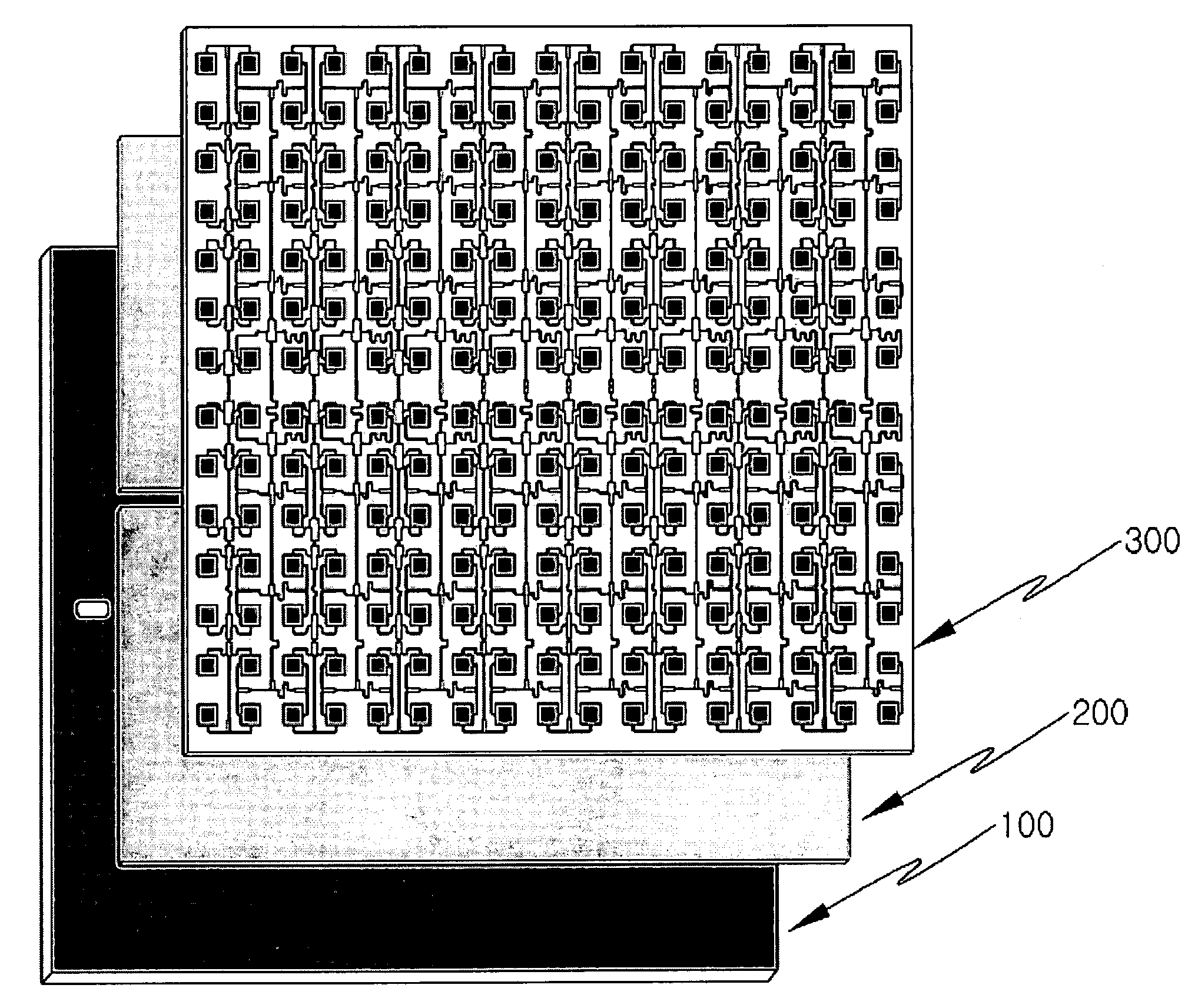
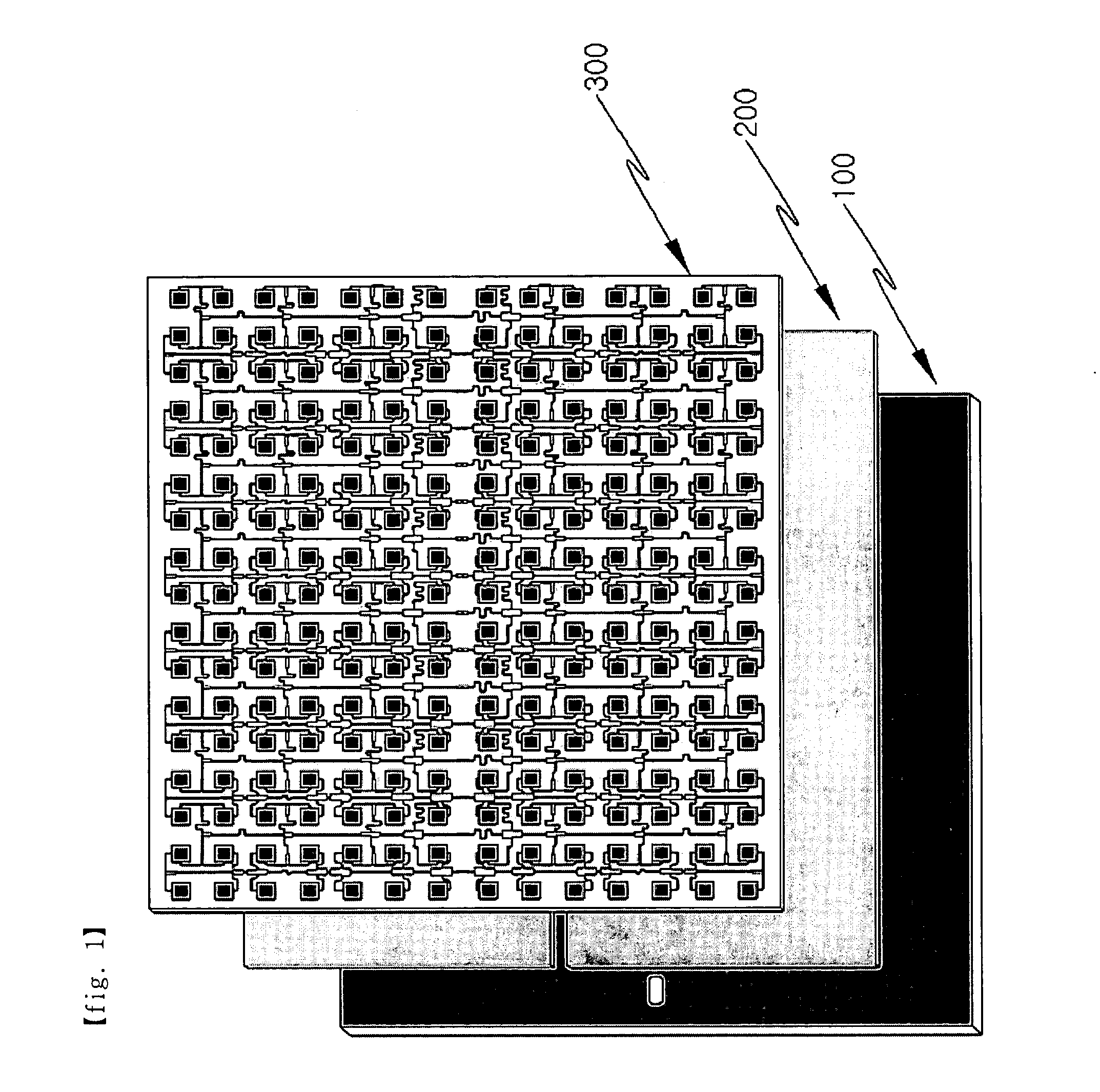
[0044]FIG. 1 is a diagram showing the construction of a multilayer planar array antenna according to an embodiment of the present invention. The multilayer planar array antenna includes a waveguide 100 configured to transmit signals, a first dielectric layer 200 stacked on the waveguide 100, and a radiating unit 300 formed in such a way that a plurality of radiating elements 310 and a plurality of radiating element feeding portions 320, which are arranged above the first dielectric layer 100, is formed thereon, and dually polarized waves are transmitted and received in a single plane.

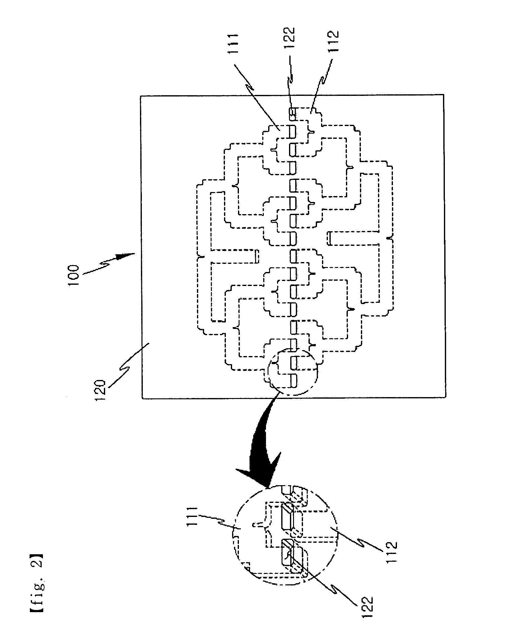
[0045]In more detail, as shown in FIG. 2, a signal feeding portion 110, which uses a metal plate having a high conductivity and feeds transmitted and received signals using a parallel feeding method, and a reflecting plate 120, on which feeding slots 122 for feeding the signals ...


PUM


Abstract

Disclosed herein is a multilayer planar array antenna. The antenna includes a waveguide, a first dielectric layer, a radiating unit, a second dielectric layer, parasitic elements, and a feeding cover unit. The waveguide is configured to transmit signals. The first dielectric layer stacked on the waveguide. The radiating unit is formed in such a way that a plurality of radiating elements and a plurality of radiating element feeding portions, which are arranged on the first dielectric layer, are formed thereon, so that a dually polarized wave is transmitted and received in a single plane. The second dielectric layer is stacked on the radiating unit. The parasitic elements are formed on the second dielectric layer to correspond to the respective radiating elements. The feeding cover unit is formed on the parasitic elements to correspond to the plurality of radiating element feeding portions.

Description

BACKGROUND OF THE INVENTION[0001]1. Field of the Invention[0002]The present invention relates generally to a multilayer planar array antenna and, more particularly, to a multilayer planar array antenna, which enables the reduction of the size thereof, extends the bandwidth thereof, and transmits and receives signals at high gain and high efficiency.[0003]2. Description of the Related Art[0004]As a technology relating to a small-sized plane antenna, including a conventional array patch antenna device, Korean Unexamined Pat. No. 2002-0015428 includes an array patch antenna element and a low-noise block down converter. The array patch antenna element includes a radiating substrate on which a plurality of slot pairs, each of which includes a first slot and a second slot that are arranged to form an angle of 180 degrees with a reflecting substrate, is formed, and on which a feeding line for supplying current to the slot pairs is formed, a lens substrate in which a plurality of lens holes...

Claims


Application Information

Patent Timeline
IPC IPC(8): H01Q1/38
CPCH01Q21/0087H01Q21/24H01Q21/065H01Q1/38H01Q13/22
Inventor CHO, TAE-KWANBANG, YOUNG-SUP
Owner MOTONIX
Why Eureka
Try Eureka