LED device for wide beam generation

Active Publication Date: 2007-08-30
SIGNIFY HOLDING B V
View PDF44 Cites 276 Cited by
  • Summary
  • Abstract
  • Description
  • Claims
  • Application Information

AI Technical Summary

Benefits of technology

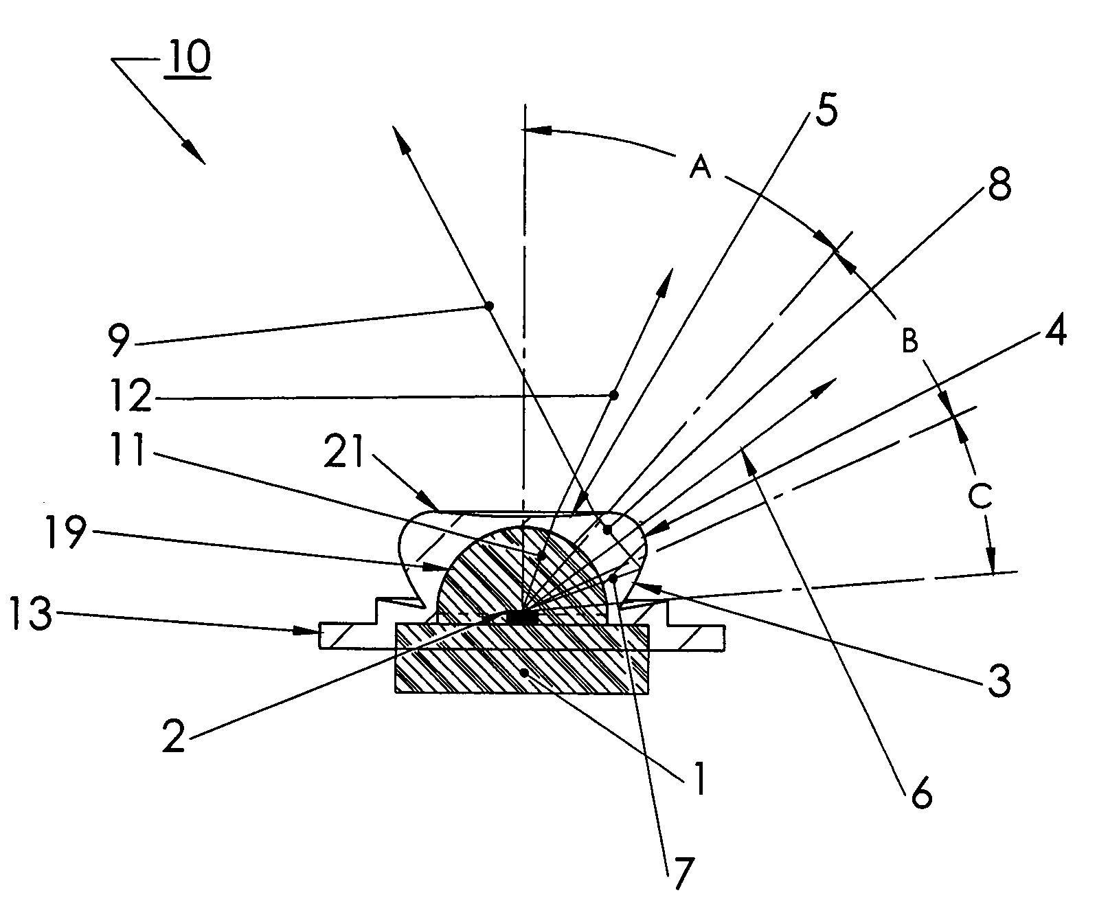
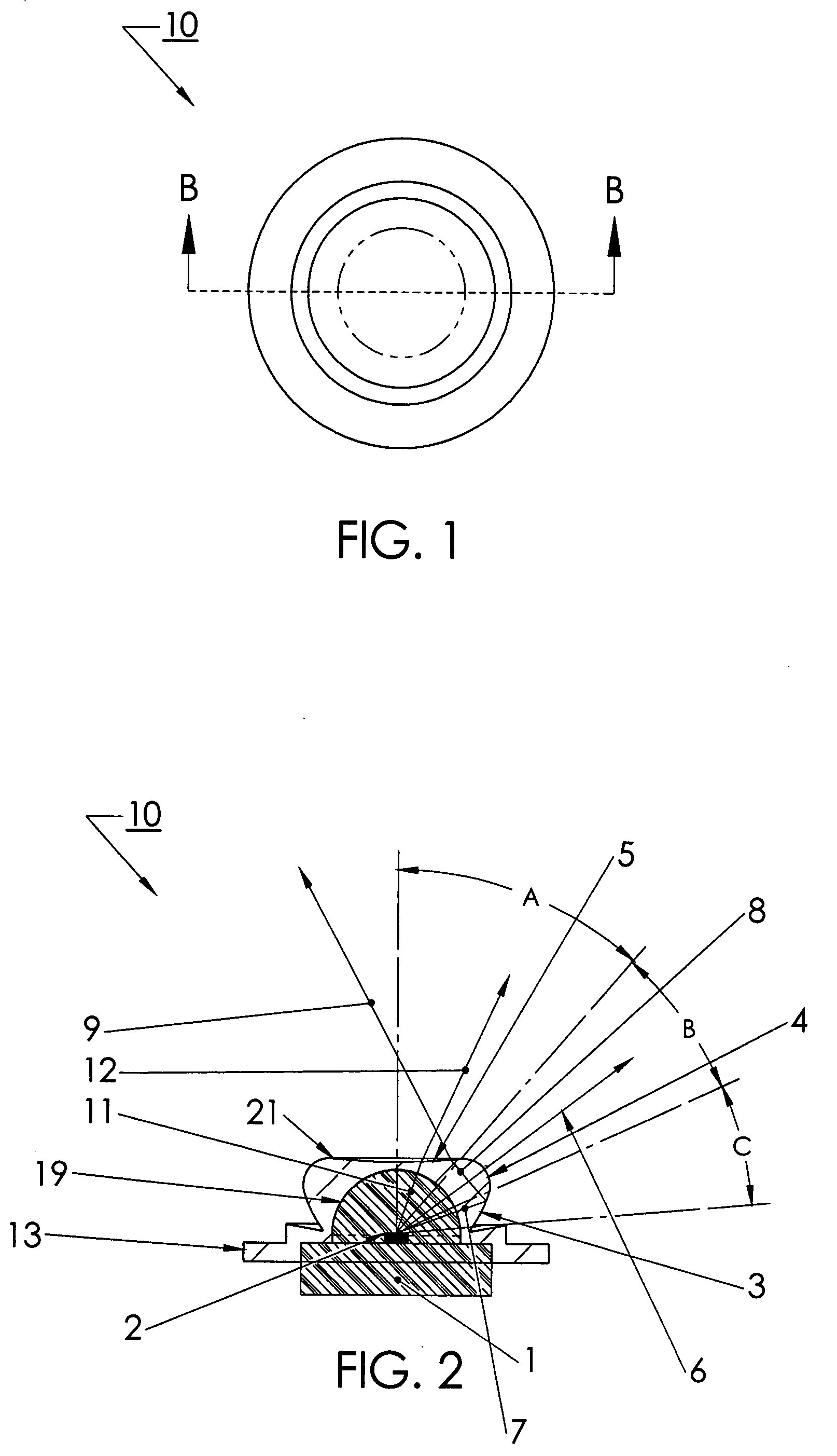
[0033]The lens comprises a transparent or translucent “blob-like” or dimpled-puddle shape, which produces a high angle intensity wide beam without adding any additional surface losses, either reflective or refractive than the LED would cause itself in this configuration of the invention. Almost all the energy of the LED is directed into the beam without losses much in excess of those

Problems solved by technology

The initial investment cost of LED illumination is expensive when compared with traditional lighting means using cost per lumen as the metric.
While this may change over time, this high cost places a premium on collection and distribution efficiency of the LED optical system.
The dazzling city lights seen from aircraft and

Method used


Image

  • LED device for wide beam generation
  • LED device for wide beam generation
  • LED device for wide beam generation

Examples


Example

[0077]The invention and its various embodiments can now be better understood by turning to the following detailed description of the preferred embodiments which are presented as illustrated examples of the invention defined in the claims. It is expressly understood that the invention as defined by the claims may be broader than the illustrated embodiments described below.

DETAILED DESCRIPTION OF THE PREFERRED EMBODIMENTS

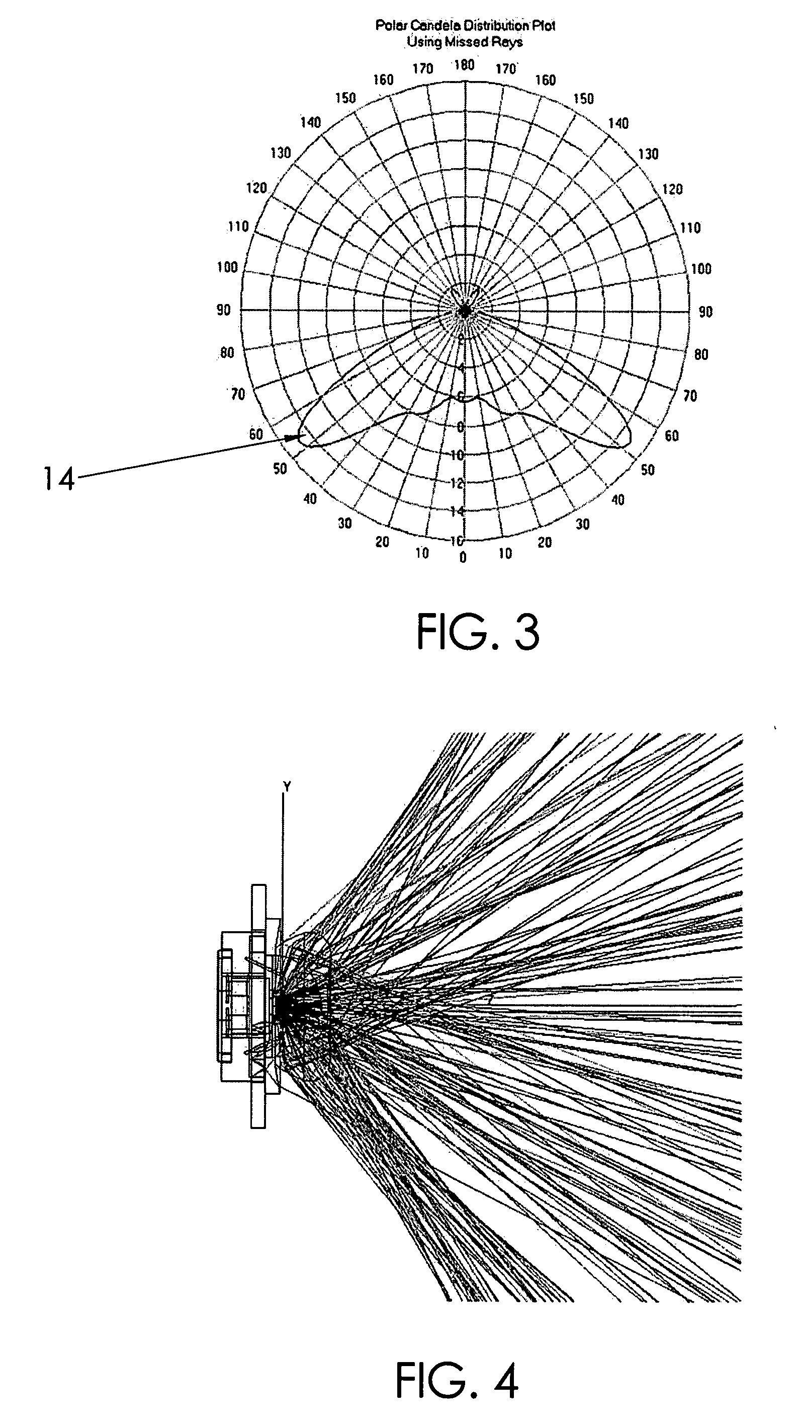
[0078]Before turning to the specifically illustrated examples shown in the drawings, we consider the various embodiments of the invention in more general terms. The illustrated embodiment of the invention uses light emitting diodes (LED), or other light sources, in a device that directs the energy from the LED into a smooth, broad beam. A broad beam can best be described as a beam which provides an illumination pattern on the surface intended to be illuminated, (e.g. the street, sidewalk, wall, etc.) that has a 50 percent maximum foot-candle measurement at an angle gr...


PUM


Abstract

An apparatus and method is characterized by providing an optical transfer function between a predetermined illuminated surface pattern, such as a street light pattern, and a predetermined energy distribution pattern of a light source, such as that from an LED. A lens is formed having a shape defined by the optical transfer function. The optical transfer function is derived by generating an energy distribution pattern using the predetermined energy distribution pattern of the light source. Then the projection of the energy distribution pattern onto the illuminated surface is generated. The projection is then compared to the predetermined illuminated surface pattern to determine if it acceptably matches. The process continues reiteratively until an acceptable match is achieved. Alternatively, the lens shape is numerically or analytically determined by a functional relationship between the shape and the predetermined illuminated surface pattern and predetermined energy distribution pattern of a light source as inputs.

Description

RELATED APPLICATIONS[0001]The present application is related to U.S. Provisional Patent Application Ser. No. 60 / 777,310, filed on Feb. 27, 2006; U.S. Provisional Patent Application Ser. No. 60 / 838,035, filed on Aug. 15, 2006; and U.S. Provisional Patent Application Ser. No. 60 / 861,789, filed on Nov. 29, 2006, each of which are incorporated herein by reference and to which priority is claimed pursuant to 35 USC 119.BACKGROUND OF THE INVENTION[0002]1. Field of the Invention[0003]The invention relates to the field of apparatus and methods for using light emitting diodes (LEDs) or other light sources to generate predetermined wide profile two dimensional illumination patterns using a light source which has been optically modified to provide a corresponding wide profile beam or a flat array of multiple ones of such modified light sources.[0004]2. Description of the Prior Art[0005]The initial investment cost of LED illumination is expensive when compared with traditional lighting means us...

Claims


Application Information

Patent Timeline
IPC IPC(8): B60Q1/26H01L33/58
CPCF21K9/00F21S8/086F21V5/04F21W2131/103F21Y2101/02G02B27/0012F21V13/04F21V31/005G02B19/0071G02B19/0028G02B19/0061F21S8/085H01L33/58F21Y2105/16F21Y2115/10F21K9/69F21V23/005F21V7/0091F21V19/02F21V29/70
Inventor HOLDER, RONALD L.RHOADS, GREG
Owner SIGNIFY HOLDING B V
Why Eureka
Try Eureka