
Steam separator, boiling water reactor and swirler assembly

a technology of swirler and steam separator, which is applied in the direction of separation process, nuclear elements, greenhouse gas reduction, etc., can solve the problems of pressure loss and the improvement of steam separation capability, and achieve the effects of reducing pressure loss, increasing moisture content, and reducing quality

Active Publication Date: 2007-08-30
HITACHI-GE NUCLEAR ENERGY LTD
View PDF8 Cites 21 Cited by
  • Summary
  • Abstract
  • Description
  • Claims
  • Application Information

AI Technical Summary

Benefits of technology

The present invention provides a steam separator with high steam separation capability and small pressure loss. By using an auxiliary swirler and controlling pressure loss in the steam separator, the quality of the steam and water at the outlet of the steam separator is not reduced, and the core flow rate and thermal power can be increased. This allows for efficient separation of steam and water even at increased core flow rates and reactor power.

Problems solved by technology

However, improvement in steam separation capability is associated with pressure loss.

Method used


Image

  • Steam separator, boiling water reactor and swirler assembly
  • Steam separator, boiling water reactor and swirler assembly
  • Steam separator, boiling water reactor and swirler assembly

Examples


Embodiment Construction

[0033]The following is a description of an embodiment of the present invention with reference to the drawings. First, a steam separator of this embodiment will be described. A schema of a structure of a forced circulation BWR or a natural circulation BWR which uses the steam separator will be described.

[0034][Structure of Steam Separator]

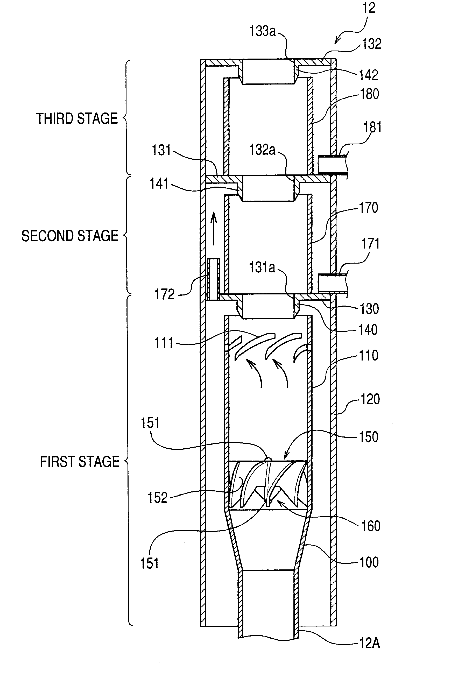
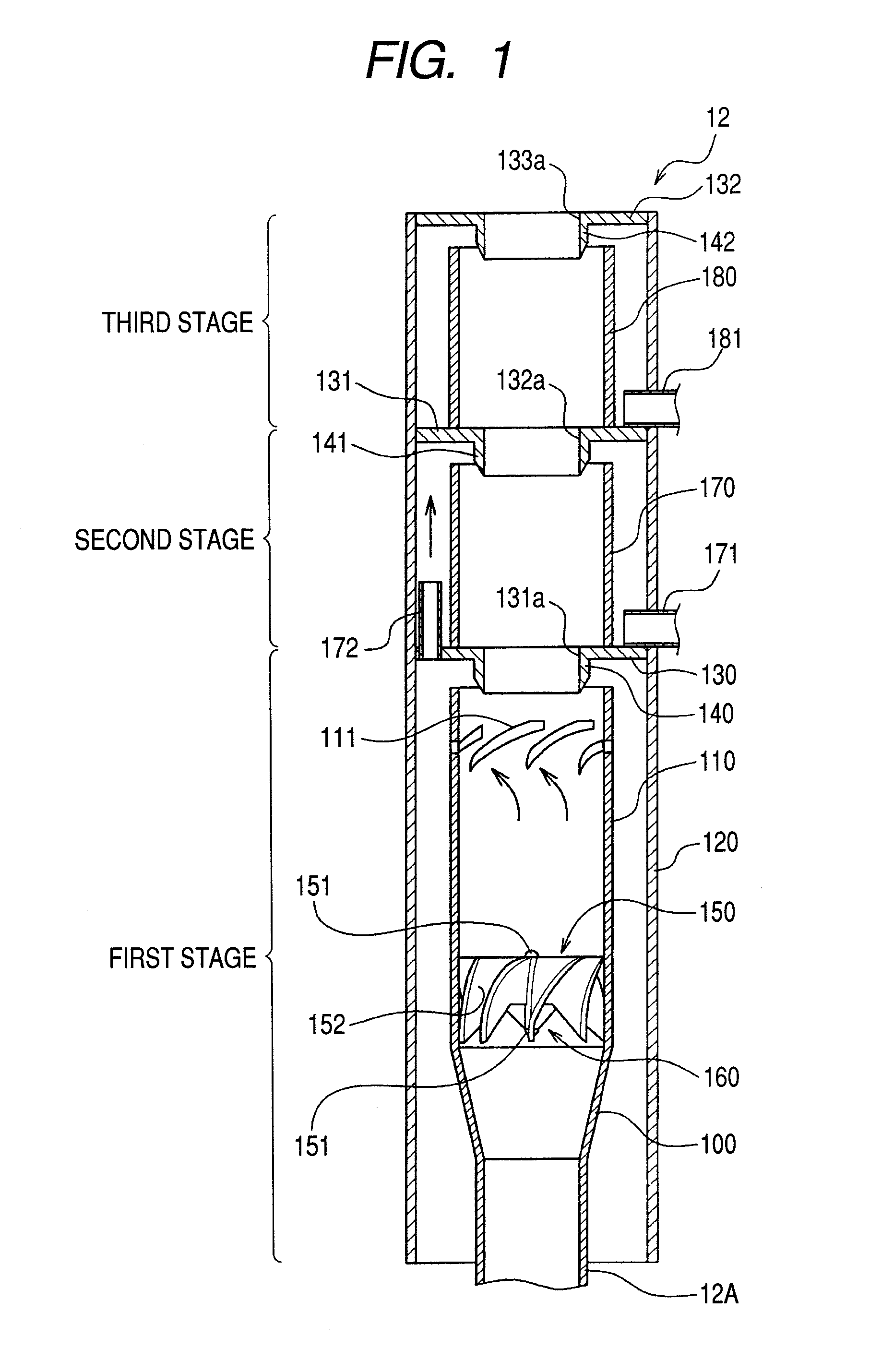
[0035]The structure of the steam separator of this embodiment will be described. FIG. 1 shows a longitudinal section of the steam separator of this an embodiment. The steam separator 12 passes the two-phase flow of cooling water (coolant) and steam ascending from a core (not shown), and separates the two-phase flow into the cooling water and the steam. The separated cooling water is re-circulated to the core. The separated steam is supplied to the turbine (not shown).

[0036]The steam separator 12 mainly comprises a stand-pipe 12b, a diffuser 100, a first stage inner cylinder 110, outer cylinders (first stage, second stage and third stage) 120, a firs...


PUM

PropertyMeasurementUnit
areaaaaaaaaaaa
diameteraaaaaaaaaa
inner diameteraaaaaaaaaa

Abstract

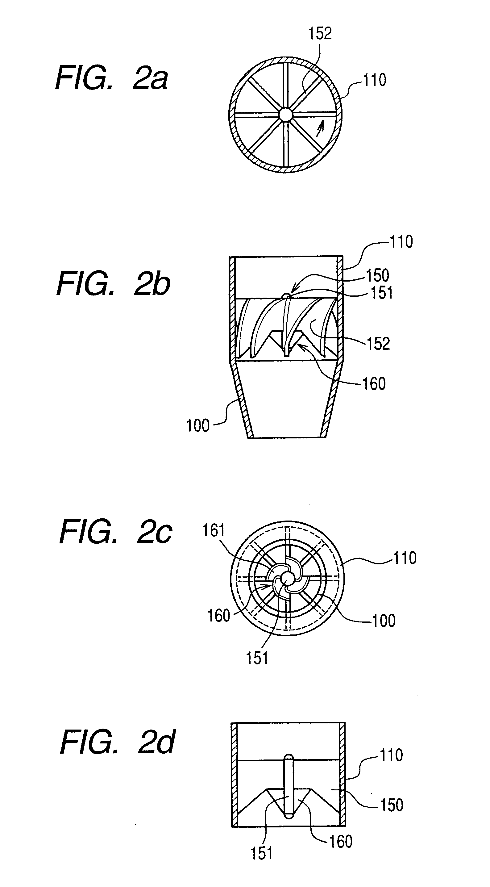
A steam separator comprises an outer main swirler and an inner auxiliary swirler which is smaller than the main swirler. The swirlers are provided so as to be concentric on the inner wall at the lower side of the first stage inner cylinder. In the steam separator, when the gas-liquid two-phase flow which flows in the vicinity of the axial center of the first stage inner cylinder passes the auxiliary swirler, it is separated into steam and water by the centrifugal force. The separated water (droplets) is introduced into the main swirler. When the separated water (droplets) passes the main swirler, it is separated at the inner wall side of the first stage inner cylinder by the centrifugal force.Pressure loss in a steam separator is reduced and steam separation capability is increased without increasing the moisture from the steam separator.

Description

CLAIM OF PRIORITY[0001]The present application claims priority from Japanese application serial no. 2006-053713, filed on Feb. 28, 2006, the content of which is hereby incorporated by reference into this application.BACKGROUND OF THE INVENTION[0002]The present invention relates to a boiling water reactor (BWR), and to the steam separator used in this boiling water reactor and to the swirler assembly being included in the steam separator.[0003]Generally, in a BWR, thermal energy is generated at a core, and due to the coolant (light water) is boiled. The steam generated at that time is supplied to a turbine. The steam rotates the turbine directly to cause power generation. In the reactor pressure vessel of this BWR, a core is disposed at the lower side, and a steam separator is disposed above the core. Two-phase flow including steam and water generated by the light water boiling in the core is introduced to the steam separator. The two-phase flow of steam and water is separated by the...

Claims


Application Information

Patent Timeline
Patent Type & Authority Applications(United States)
IPC IPC(8): G21C9/00
CPCB01D45/16B04C3/00B04C2003/006Y02E30/31G21C1/084G21Y2002/201G21Y2004/302F22B37/327Y02E30/30
Inventor CHAKI, MASAOMURASE, MICHIOISHIDA, NAOYUKI
Owner HITACHI-GE NUCLEAR ENERGY LTD
Learn More