Condenser microphone

a condenser microphone and microphone technology, applied in the field of condenser microphones, can solve the problems of complex manufacturing process, and degrading so as to avoid electrostatic capacitance, improve the sensitivity of the condenser microphone, and the capacity is unchanged

Active Publication Date: 2007-08-30
INFINEON TECH AG
View PDF6 Cites 36 Cited by
  • Summary
  • Abstract
  • Description
  • Claims
  • Application Information

AI Technical Summary

Benefits of technology

[0008] It is an object of the present invention to provide a condenser microphone having a high sensitivity, which can be easily produced by way of a simple semiconductor manufacturing process.
[0009] It is another object of the present invention to provide a condenser microphone and its manufacturing method, which realizes a high sensitivity by use of a diaphragm whose bent portion has a high strength.

Problems solved by technology

This makes the manufacturing process complicated.
This degrades the sensitivity of the condenser microphone.
The bent portion is formed using a single thin film, which is generally deposited on the surface of a step portion formed in a sacrifice layer; hence, the thickness thereof becomes small as it approaches the bottom of the step portion because the step portion is difficult to be deposited and is thus reduced in density.
In other words, it is very difficult to increase the sensitivity by increasing the height difference of the bent portion while maintaining the satisfactory strength of the diaphragm.

Method used


Image

  • Condenser microphone
  • Condenser microphone
  • Condenser microphone

Examples


first embodiment

1. First Embodiment

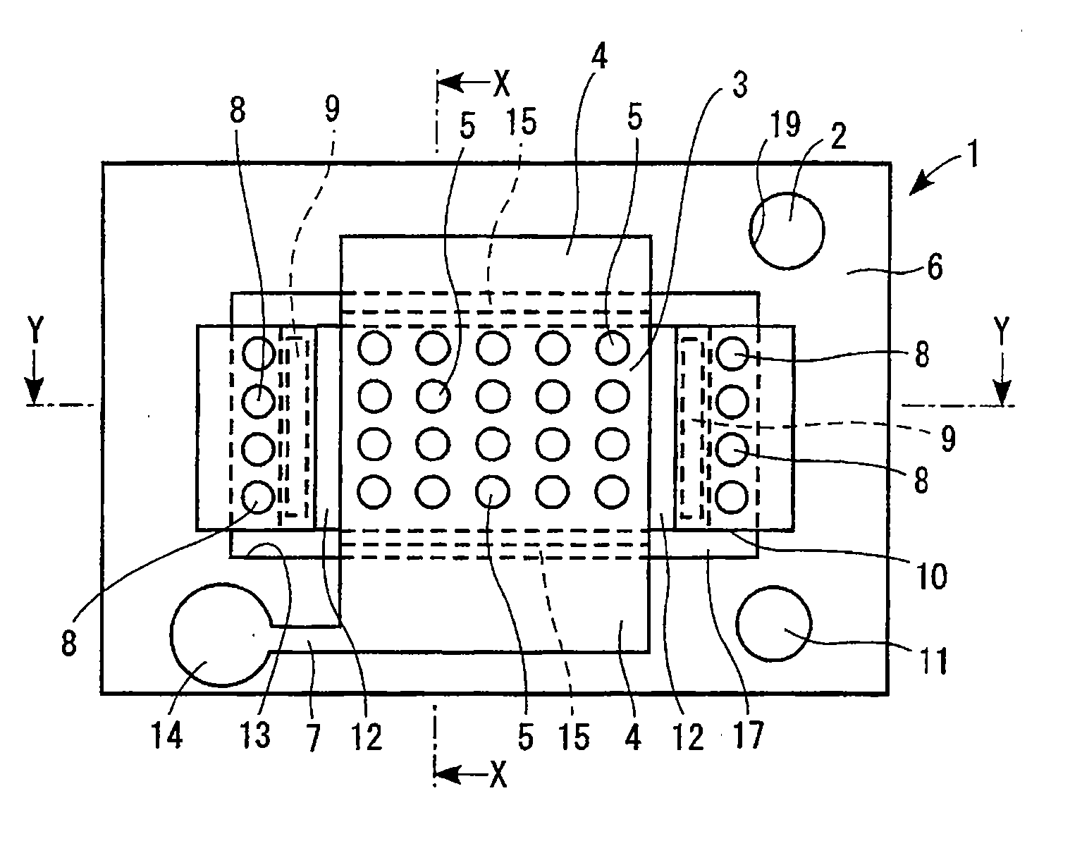
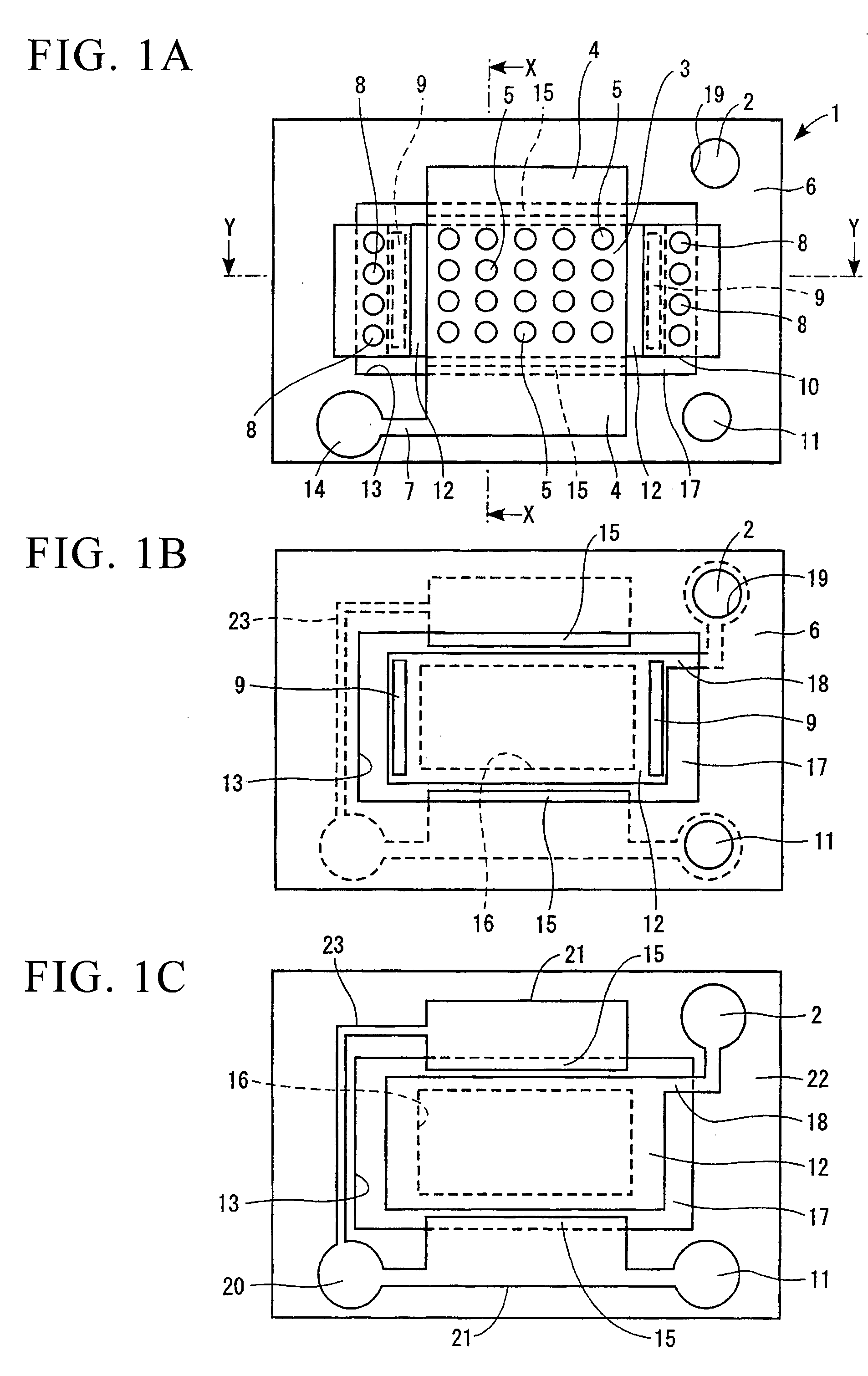
[0122] A first embodiment is directed to a condenser microphone, i.e., a silicon capacitor microphone, which is produced by way of a semiconductor manufacturing process, wherein sound is transmitted to a diaphragm via a plate and is thus converted into electric signals. FIG. 1A, FIG. 2A, and FIG. 2B show a sensing portion of a condenser microphone 1; specifically, FIG. 1 is a plan view, FIG. 2A is a cross-sectional view taken along line Y-Y (showing a Y-axis direction), and FIG. 2B is a cross-sectional view taken along line X-X (showing an X-axis direction). FIG. 2B shows the circuitry of a detecting portion of the condenser microphone 1. FIG. 1B is a plan view of the condenser microphone 1 in which a plate 3 and a fourth film forming supports 10 are excluded from the illustration of FIG. 1A. FIG. 1C is a plan view of the condenser microphone 1 in which a third film forming a second spacer 6 and third spacers 9 is excluded from the illustration of FIG. 1B.

(a) Mu...

second embodiment

2. Second Embodiment

[0152] Next, a condenser microphone of a second embodiment of the present invention will be described in detail with reference to FIGS. 7A, 7B, and 8, wherein FIG. 8 is a plan view showing a condenser microphone 101; FIG. 7A is a cross-sectional view taken along line B1-B1 in FIG. 8; and FIG. 7B is a cross-sectional view taken along line A1-A1 in FIG. 8. The condenser microphone 101 is a silicon capacitor microphone, which is manufactured by way of semiconductor manufacturing process. The condenser microphone 101 includes a sensing portion (see FIGS. 7A and 7B) and a detecting portion (see the circuitry shown in FIG. 7A).

(a) Constitution of Sensing Portion

[0153] As shown in FIGS. 7A and 7B, the condenser microphone 101 includes a diaphragm 110, a back plate 130, and supports 140.

[0154] Both ends of the diaphragm 110 are supported by the supports 140. The diaphragm 110 has a multilayered structure (see FIG. 7B), wherein a center portion 112 of the diaphragm 11...

third embodiment

3. Third Embodiment

[0198]FIGS. 17A, 17B, 18A, and 18B show the constitution of a condenser microphone 401 in accordance with a third embodiment of the present invention, wherein FIG. 17A is a cross-sectional view take along line B1-B1 in FIG. 18A; FIG. 17B is a cross-sectional view taken along line Al -Al in FIG. 18A; and FIG. 18B is a cross-sectional view taken along line B2-B2 in FIG. 17B.

[0199] Similar to the aforementioned condenser microphones 1 and 101, the condenser microphone 401 is a silicon capacitor microphone that is produced by way of the semiconductor manufacturing process. The condenser microphone 401 includes a sensing portion (see FIGS. 17A and 17B) and a detecting portion (see the circuitry shown in FIG. 17A).

(a) Constitution of Sensing Portion

[0200] As shown in FIGS. 17A and 17B, the sensing portion of the condenser microphone 401 includes a diaphragm 410, a back plate 430, and supports 440.

[0201] The diaphragm 410 is formed by a prescribed portion of a condu...


PUM


Abstract

A condenser microphone includes a substrate having a cavity, first and second spacers defining an opening, a diaphragm having a rectangular shape positioned inside of the opening, and a plate having a rectangular shape positioned just above the diaphragm. Plate joint portions integrally interconnected with two sides of the plate are directly attached onto the second spacer. Supports, which are attached onto the second spacer across the opening and project inwardly of the opening, are connected to the prescribed portions of the diaphragm via third spacers relatively to the other two sides of the plate. The center portion of the diaphragm can be designed in a multilayered structure, and the peripheral portion can be bent outwardly. In addition, both ends of the diaphragm are fixed in position, while free ends of the diaphragm vibrate due to sound waves.

Description

TECHNICAL FIELD [0001] The present invention relates to condenser microphones (or capacitor microphones) having diaphragms adapted to micro-electromechanical systems (MEMS). The present invention also relates to manufacturing methods of condenser microphones and manufacturing methods of diaphragms included in condenser microphones. [0002] This application claims priority on Japanese Patent Application No. 2006-96703 (filed Mar. 31, 2006), Japanese Patent Application No. 2006-59041 (filed Mar. 6, 2006), and Japanese Patent Application No. 2006-48183 (filed Feb. 24, 2006), the contents of which are incorporated herein by reference. BACKGROUND ART [0003] Conventionally, various types of condenser microphones (or capacitor microphones) have been developed and produced by way of manufacturing processes of semiconductor devices. A typical example of a condenser microphone includes a diaphragm, which vibrates due to sound waves, and a plate, which is positioned opposite to the diaphragm vi...

Claims


Application Information

Patent Timeline
Patent Type & Authority Applications(United States)
IPC IPC(8): H04R25/00H04R11/02
CPCB81B3/0072B81B2201/0257H04R2499/11H04R19/005B81B2203/0127H04R19/04H04R31/006
Inventor SUZUKI, TOSHIHISASUZUKI, YUKITOSHIYAGUCHI, NARIYASUSAKURAUCHI, KAZUSHI
Owner INFINEON TECH AG
Why Eureka
Try Eureka