Flow-Controlled Wind Rotor

a flow-controlled, wind rotor technology, applied in the direction of propellers, propulsive elements, water-acting propulsive elements, etc., can solve the problems of low efficiency of darrieux rotors, only a limited movement of blades, and considerable noise, and achieve the effect of simple control mechanisms

Inactive Publication Date: 2007-08-30
VENTUS SPOLKA Z O O
View PDF5 Cites 18 Cited by
  • Summary
  • Abstract
  • Description
  • Claims
  • Application Information

AI Technical Summary

Benefits of technology

[0008] An objective of the invention is to create a flow-controlled rotor with a vertical axis of rotation, using the power of wind aerodyn

Problems solved by technology

This rotor includes, however, blades having only a limited movement.
The efficiency of Darrieux rotors is low.
This results in considerable noise and a poor use of the working area of th

Method used


Image

  • Flow-Controlled Wind Rotor
  • Flow-Controlled Wind Rotor
  • Flow-Controlled Wind Rotor

Examples


Embodiment Construction

[0017] The invention is explained hereinbelow more closely in its preferred embodiments on the basis of the drawings.

[0018] It shows:

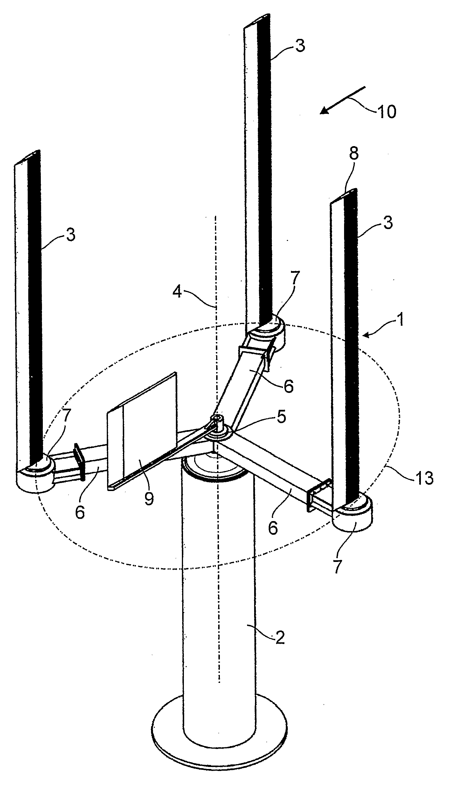
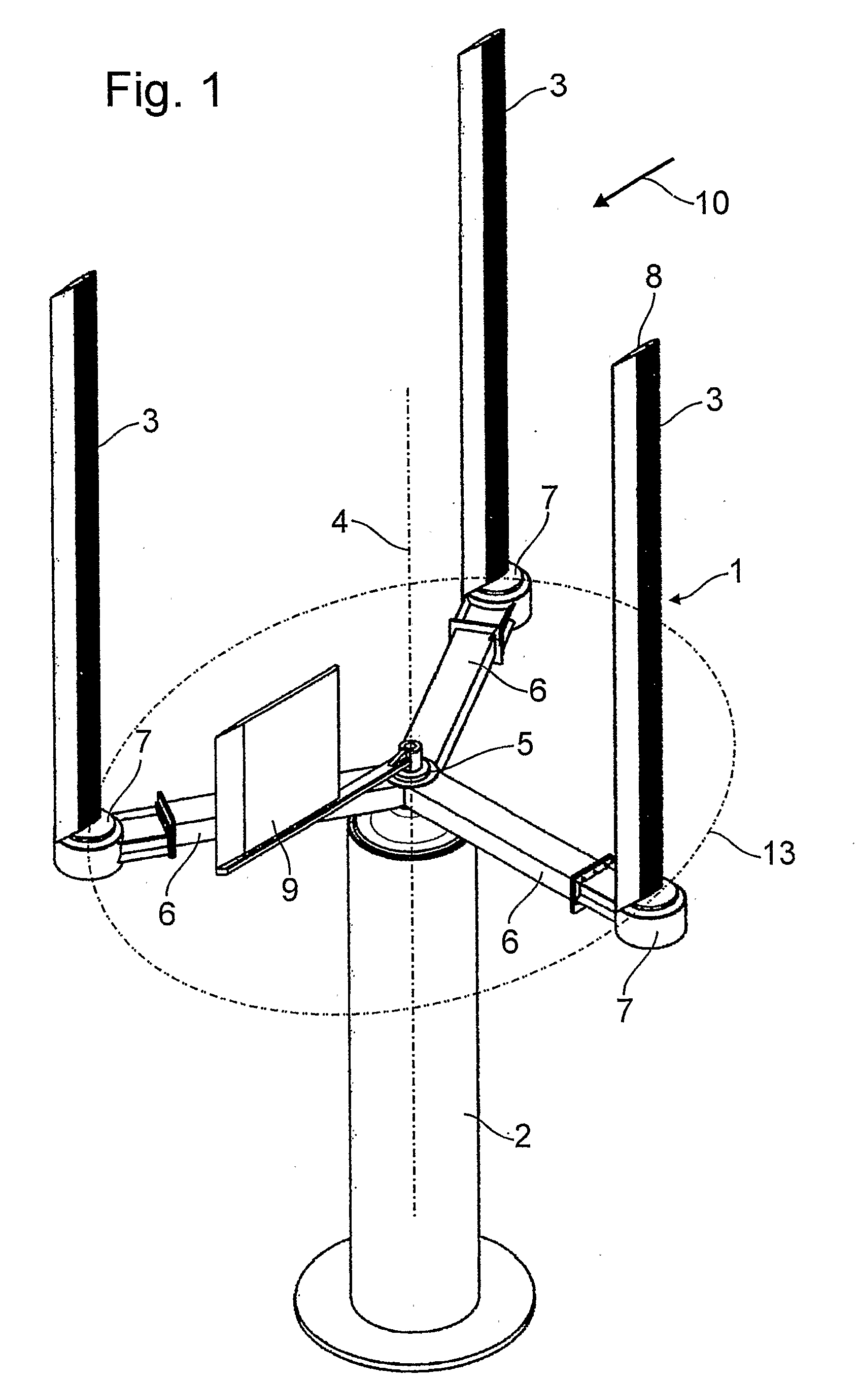
[0019]FIG. 1 An isometric overview of the wind motor with a flow-controlled rotor,

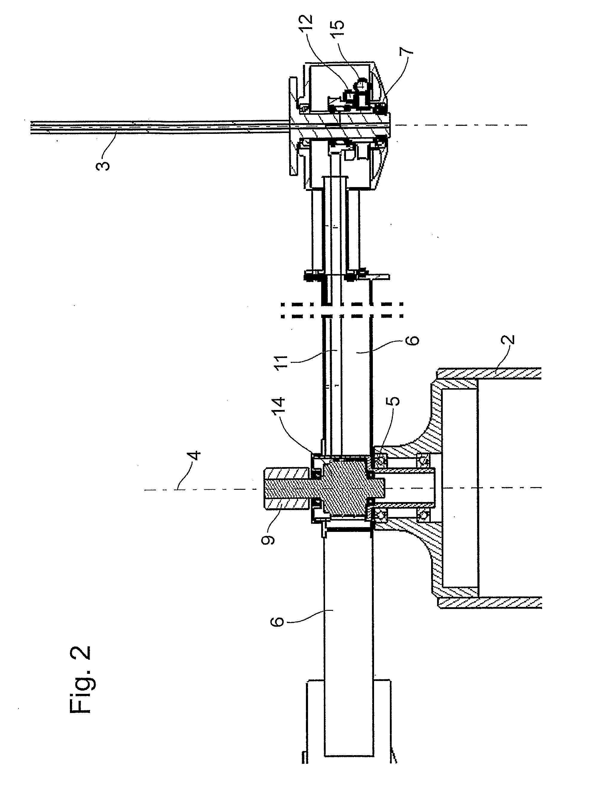
[0020]FIG. 2 An illustration of the proper shape of control mechanisms for blade alignment,

[0021]FIG. 3 A schematic illustration of the blade control depending on the angle of rotation in two selected positions.

[0022] The wind motor in FIG. 1 comprises of a tower 2, with a wind rotor 1 rotationally disposed on the main bearing 5. The wind rotor 1 comprises three blades 3 rotating around a central vertical axis 4, the blades being parallel to the vertical axis 4 and connected by crossbars 6. The blades 3 are disposed freely rotatably in the bearings 7 at the ends of the crossbars 6. The blades 3 revolve firstly with the crossbars 6 around the central vertical axis of rotation 4, and secondly around themselves in the bearings 7 at the ends of the crossbeams 6. The blad...


PUM


Abstract

Disclosed in a wind rotor (1) comprising one or more blades (3) rotating around a vertical, central axis (4) within a main bearing (5), said blades being parallel to said vertical axis (4), said blades being connected via crossbars (6), said blades being disposed freely rotatably in bearings (7), and said blades being orientable by means of a wind vane (9). Said blades (3) comprise a symmetrical aerodynamic profile (8) over their entire cross-section. Said rotor comprises a primary control mechanism (11), which is controlled by said wind vane (9) and aligns said profiles (8) of said blade(s) (3) along the wind direction (10) at each point of their trajectory (13) around the central vertical axis (4), said blades being disposed on said crossbars (6), and a secondary control mechanism (12), which aligns the longitudinal axes of said profiles (8) of said blade(s) (3) to the wind (10) at each point of their trajectory (13) around the central vertical axis (4) so as to produce an optimum aerodynamic force depending on the rotation angle of the crossbars (6) with respect to the wind vane (9) and the rotation velocity of the crossbars (6).

Description

[0001] The invention concerns a flow-controlled wind rotor adjustable by a wind vane and having a vertical axis of rotation and rotating blades revolving around the axis. DESCRIPTION OF THE PRIOR ART [0002] Wind rotors with vertical rotation axes are known in the art as Savonius rotors, Darrieux rotors, vertical dual rotors, or Jackson rotors. Jackson rotors have not only a vertical axis, but comprise also blade-like plates, revolving around the vertical axis and simultaneously turning around their own axis by 180°. [0003] Based on the design of Jackson rotors, solutions have been developed and described, e.g., in specifications of German Patents DE 198 47 469 A, DE 81 119 10 U1 and DE 39 18 184A1. [0004] The invention disclosed in DE 30 18 211 C2 has a design similar to that of a Darrieux rotor. This rotor includes, however, blades having only a limited movement. The efficiency of Darrieux rotors is low. They require strong winds and frequently an auxiliary starter. [0005] Wind mot...

Claims


Application Information

Patent Timeline
IPC IPC(8): B63H1/06F03B17/06F03D3/06
CPCF03B17/067F03D3/068F05B2240/214Y02E10/74F05B2260/79Y02E10/28Y02E10/38F05B2260/72Y02E10/20Y02E10/30F03B17/062F03B17/065F03D3/005
Inventor WARSZEWSKI, JAROSLAW
Owner VENTUS SPOLKA Z O O
Why Eureka
Try Eureka