Signal-processing unit for fluxgate magnetometers

a technology of fluxgate magnetometer and signal processing unit, which is applied in the direction of mechanical measurement arrangement, mechanical roughness/irregularity measurement, instruments, etc., can solve the problems of limiting the accuracy of target magnetic field measurement and/or the reliability of an apparatus, and the inability to integrate analog circuits

Inactive Publication Date: 2007-08-30
DENSO CORP
View PDF5 Cites 12 Cited by
  • Summary
  • Abstract
  • Description
  • Claims
  • Application Information

AI Technical Summary

Benefits of technology

[0033] In view of the background, an object of at least one aspect of the present invention is to reduce an apparatus designed to use a fluxgate magnetometer in size and / or manufacturing cost.

Problems solved by technology

This may make it difficult to integrate the analog circuits 110 and 120 together with the remaining elements of the signal-processing unit 100 in / on one chip, thereby preventing an apparatus designed to use such a fluxgate magnetometer from decreasing in size and manufacturing cost.
This may limit the accuracy of measurement of a target magnetic field and / or the reliability of an apparatus designed to use such a fluxgate magnetometer.

Method used


Image

  • Signal-processing unit for fluxgate magnetometers
  • Signal-processing unit for fluxgate magnetometers
  • Signal-processing unit for fluxgate magnetometers

Examples


first embodiment

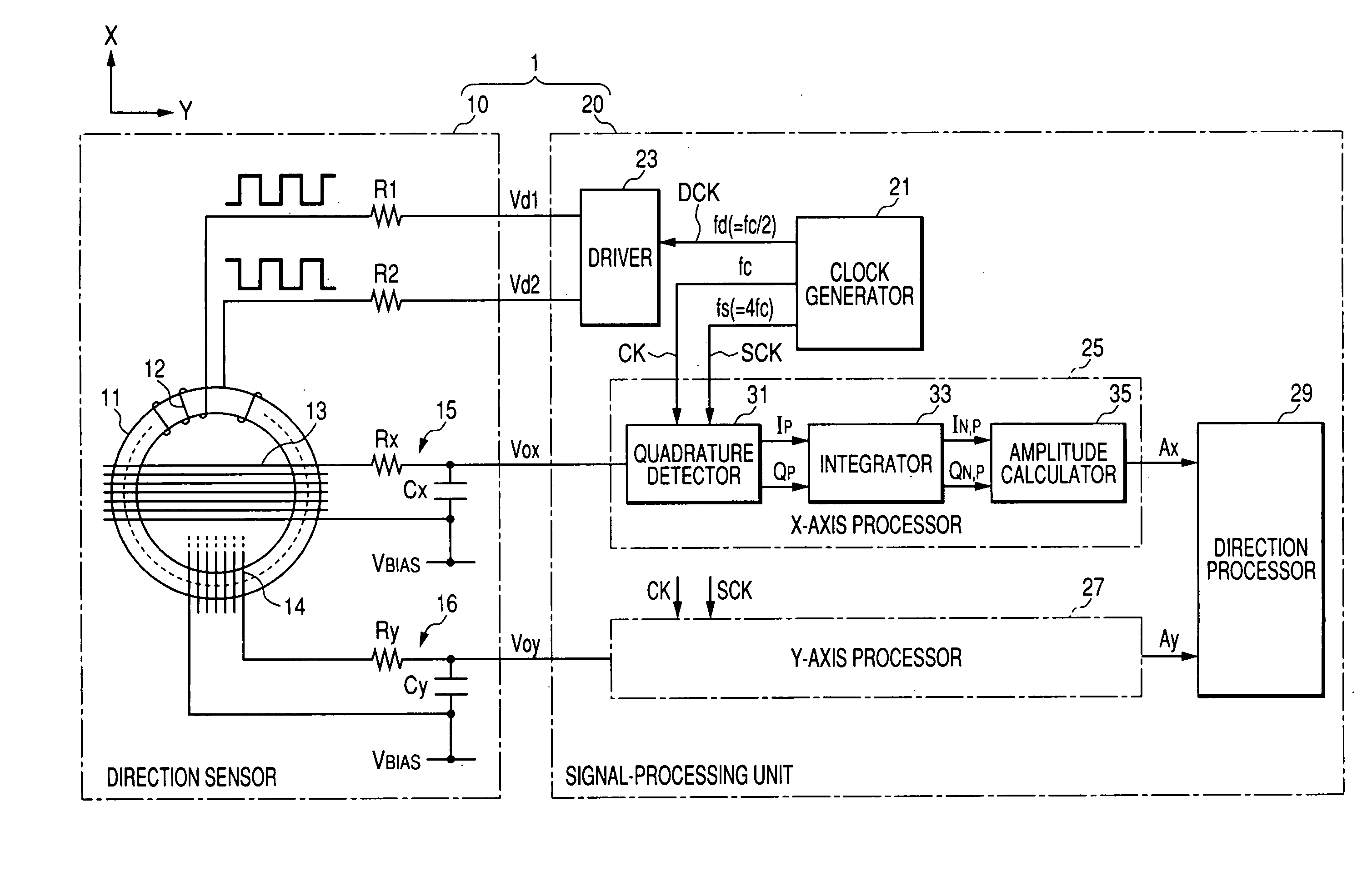
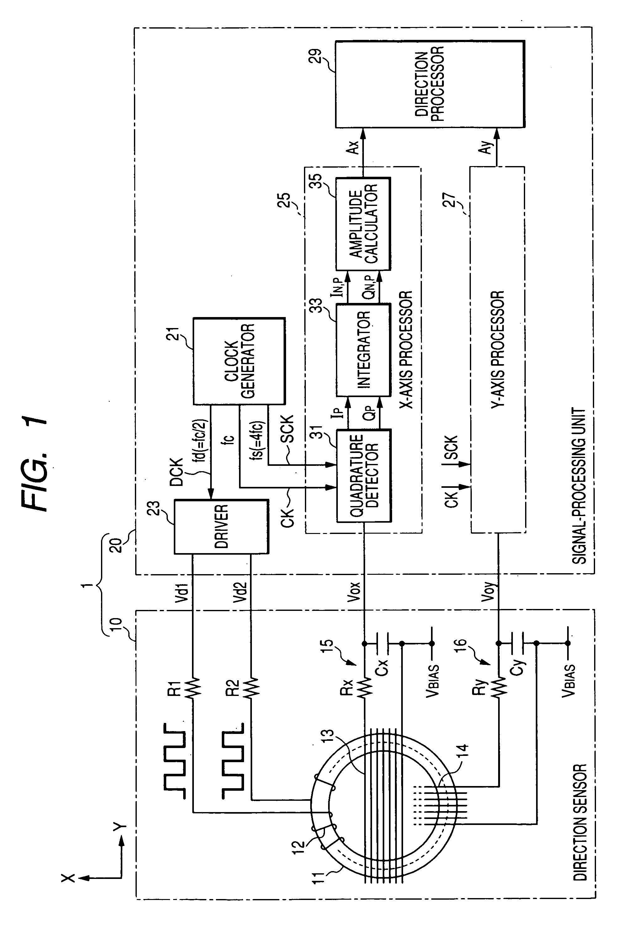
[0052] Referring to the drawings, in which like reference characters refer to like parts in several views, FIG. 1 illustrates an example of the overall structure of a direction sensor 1 according to a first embodiment to which the present invention is applied. The direction sensor 1 works to detect the earth's magnetic field as a target magnetic field, thereby obtaining information associated with directions based on the detected target magnetic field.

[0053] As illustrated in FIG. 1, the direction sensor 1 is composed of a fluxgate magnetometer 10 having two orthogonal sensing axes and a signal-processing unit 20 operative to drive the fluxgate magnetometer 10 and to process detection signals vox and voy output from the fluxgate magnetometer 10.

[0054] Because the elements of the fluxgate magnetometer 10 have been already described in the “Background of the invention” of this application, the descriptions of which will be omitted.

[0055] The signal-processing unit 20 according to t...

second embodiment

[0138]FIG. 8 illustrates an example of the overall structure of a direction sensor 1a according to a second embodiment to which the present invention is applied.

[0139] Note that the configuration of the direction sensor 1a is substantially identical with that of the direction sensor 1 according to the first embodiment except for part of a signal-processing unit 20a. For this reason, like reference characters are assigned to like parts in the direction sensors 1 and 1a according to the first and second embodiments so that descriptions of the parts will be omitted, and the different part will be mainly described.

[0140] As illustrated in FIG. 8, a clock generator 21a of the signal-processing unit 20a is operative to generate, in addition to the clock signal CK and the drive signal DCK, a sampling signal (a repetitive series of sampling clock pulses) SCK1 with a sampling frequency fs that is two times higher than the carrier frequency fc of the clock signal CK, in other words, the sam...


PUM


Abstract

A signal processing unit includes an integrating unit. The integrating unit is composed of a plurality of digital elements and operative to integrate a detection signal over every quarter of one cycle of the detection signal to generate an integration value. The integration values to be generated are represented as S1, S2, S3, S4 . . . . A calculating unit includes a plurality of digital elements and performs addition and subtraction on the generated integration values in accordance with the following equations to calculate an in-phase component and a quadrature-phase component:
Ip=S4p−3+S4p−2−S4p−1−S4p
Qp=S4p−3−S4p−2−S4p−1+S4p
    • where Ip represents the in-phase component, Qp represents the quadrature-phase component, and p=1, 2, 3 . . . . An amplitude obtaining unit obtains an amplitude of the detection signal based on the in-phase component and the quadrature-phase component.

Description

CROSS REFERENCE TO RELATED APPLICATIONS [0001] This application is based on Japanese Patent Application 2006-050301 filed on Feb. 27, 2006. This application claims the benefit of priority from the Japanese Patent Application, so that the descriptions of which are all incorporated herein by reference. FIELD OF THE INVENTION [0002] The present invention relates to signal-processing units, which are designed to process signals sensed by a fluxgate magnetometer. BACKGROUND OF THE INVENTION [0003] As highly-sensitive field sensors, fluxgate magnetometers (fluxgate sensors) are conventionally known. Such a fluxgate magnetometer is designed to sense, based on nonlinearity of a magnetization curve of a magnetic substance, the magnitude of a magnetic field to be measured; this magnetic substance is excited by an alternating magnetic field on which the magnetic field has been superimposed. [0004]FIG. 10 illustrates the schematic configuration of a fluxgate magnetometer 10 having two orthogona...

Claims


Application Information

Patent Timeline
Patent Type & Authority Applications(United States)
IPC IPC(8): G01C9/00
CPCG01C17/30
Inventor WATANABE, TAKAMOTOMASUDA, SUMIO
Owner DENSO CORP
Why Eureka
Try Eureka