Beverage bottling plant for filling bottles with a liquid beverage filling material

a beverage bottling plant and filling material technology, applied in the directions of liquid handling, packaging goods, transportation and packaging, etc., can solve the problems of significant construction effort and expense, and neither provides nor requires a control of the level of barrier fluid in the siphon seal

Active Publication Date: 2007-09-06
KHS GMBH
View PDF3 Cites 21 Cited by
  • Summary
  • Abstract
  • Description
  • Claims
  • Application Information

AI Technical Summary

Benefits of technology

[0015] An object of at least one possible embodiment of the present application is to eliminate this disadvantage and to indicate a plant for the cold-aseptic bottling of a liquid in bottles or similar container in which, in spite of the simplified construction, the presence of the sealing or barrier fluid in the at least one annular duct of the at least one siphon seal at the required level is guaranteed or substantially guaranteed a sealing system that eliminates these disadvantages. SUMMARY
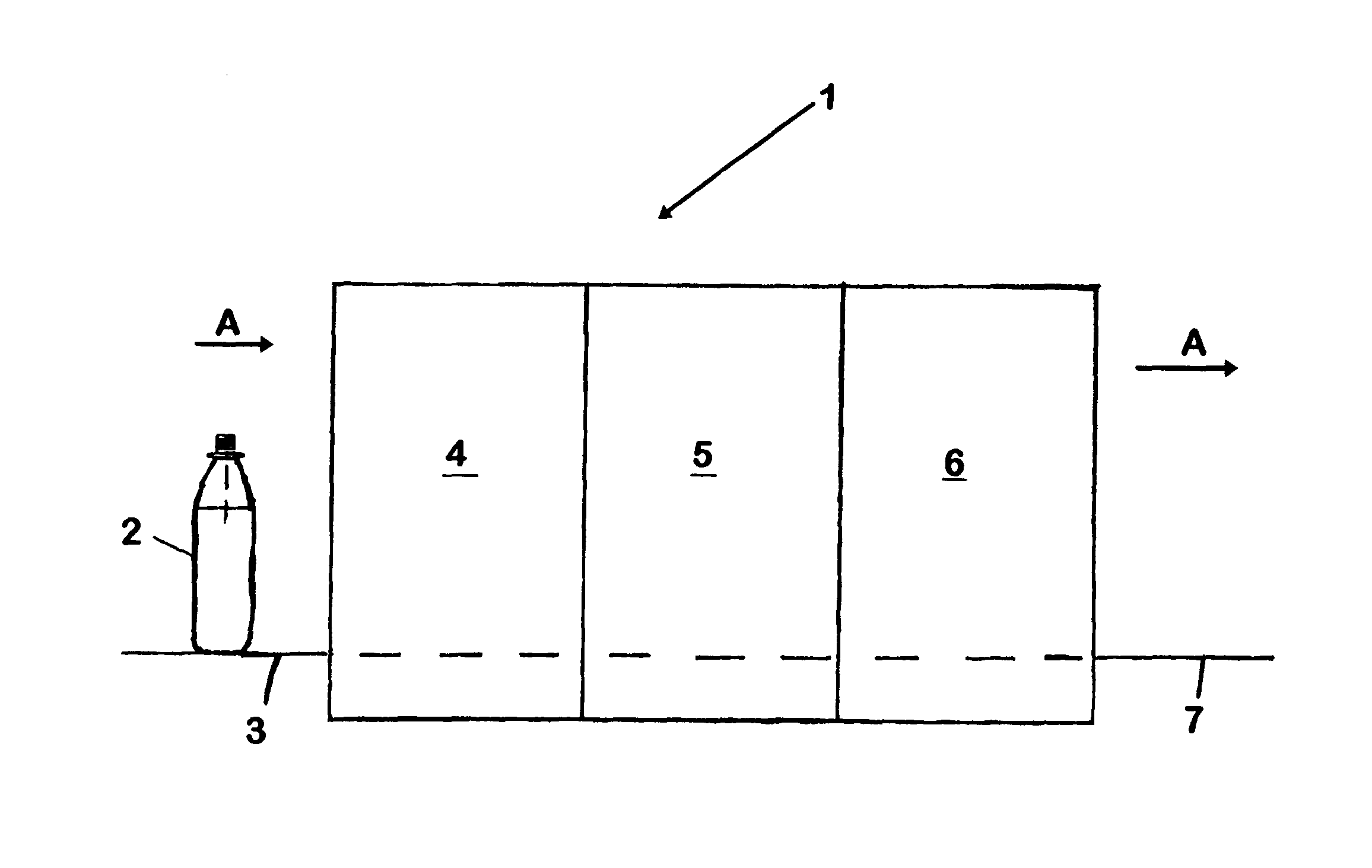
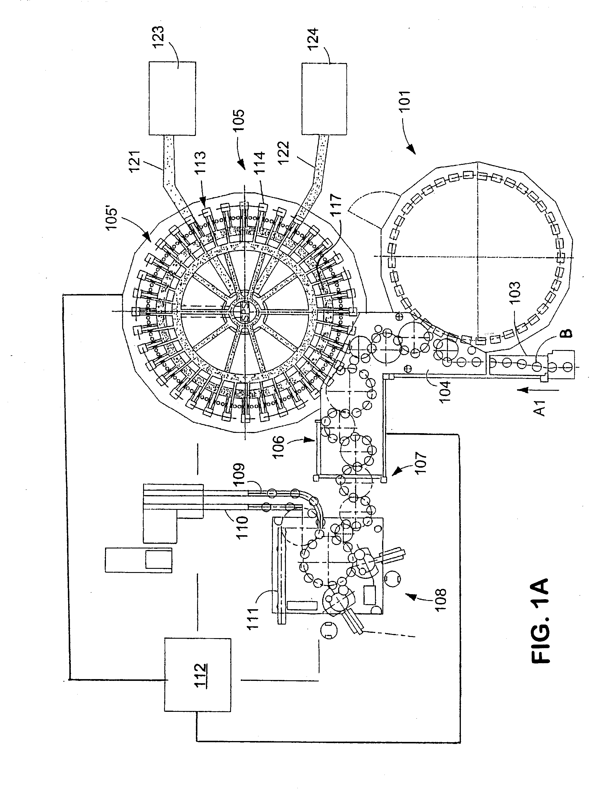
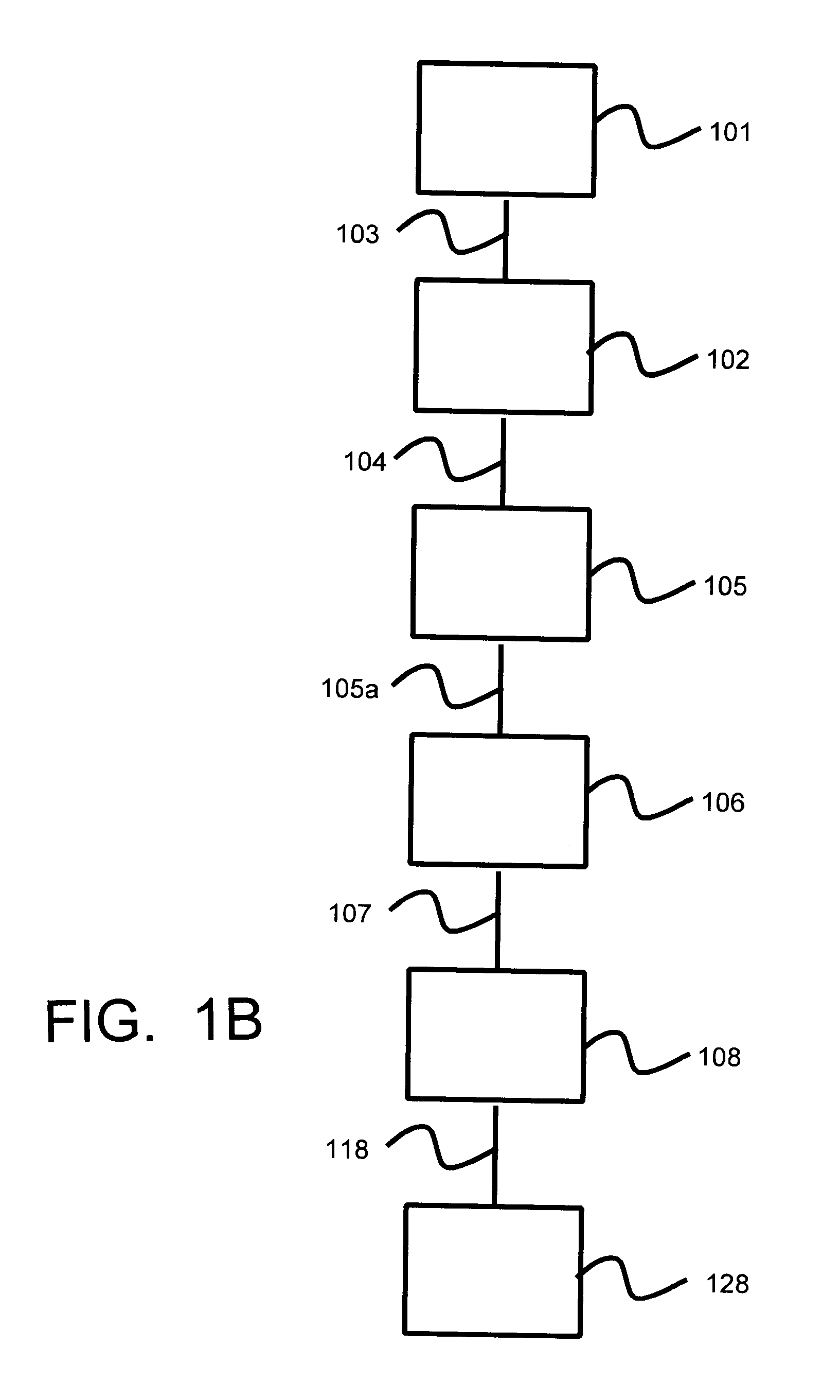
[0016] At least one possible embodiment of the present application may be a plant for the cold aseptic bottling of a liquid in bottles or similar containers, with a conveyor line on which containers are moved by at least one container handling machine in a sterile space which is separated by a housing from at least one non-sterile space, whereby the housing is formed by at least one circulating part and one stationary part, and whereby at the transition between these parts, a siphon seal is provided which makes possible the relative motion of the parts, which siphon seal comprises at least one annular duct that concentrically surrounds an axis of the circulating part to hold a sealing or barrier fluid on a ring-shaped wall element on the other part of the housing that extends into the barrier fluid located there, with at least one inlet for the feeding of the barrier fluid into the at least one annular duct and with at least one outlet for the discharge of the barrier fluid out of the annular duct, wherein the at least one outlet is realized in the form of an overflow that sets the level of the barrier fluid, and that the at least one inlet is connected with a reservoir, from which barrier fluid is fed continuously to at least one annular duct.
[0020] At least one embodiment of the present application, however, neither provides nor requires a control of the level of the barrier fluid in the siphon seals. The construction is thereby significantly simplified or substantially simplified, and operational reliability is significantly improved or essentially improved, because the electronic control circuits that regulate the level of the barrier fluid can be omitted.
[0021] In at least one possible embodiment of the present application, at least at the transition between the circulating or rotating part of the housing and the stationary part of the housing, there is or may also be at least one mechanical seal, which then comprises a sealing element on a housing that extends along a siphon seal, which sealing element interacts with a sealing surface on another part of the housing. This mechanical seal is provided on a side of the siphon seal that faces a non-sterile area, so that the siphon seal is shielded by the mechanical seal with respect to the non-sterile area. This arrangement has several additional advantages. As a result of the mechanical seal, direct contact between a barrier fluid and the non-sterile area and / or with air in the non-sterile area is prevented or substantially prevented, which among other things reduces the risk of pollution and / or microbial or bacterial contamination of the barrier fluid. The escape of barrier fluid and / or of the sterilization medium present in this fluid into the non-sterile area is also prevented or substantially prevented, as well as any or essentially any adverse effects such an escape may have such as, for example, release of odors that are unpleasant to human beings such as operating personnel, for example, who may be present in the non-sterile area.
[0022] In an additional possible embodiment of the present application, at least one siphon seal is provided with at least one discharge opening or nozzle for a cleaning or sterilization medium, so that this seal or its annular duct can then be thoroughly or substantially cleaned and / or sterilized more easily in a CIP (cleaning in place) cleaning or SIP (sterilization in place) sterilization, which is a major advantage, in a plant that has a plurality of siphon seals. Cleaning and sterilization of siphon seals in a plant that has a plurality of such seals is thereby significantly or substantially simplified and can be performed in much less time.

Problems solved by technology

Because of design and construction requirements, such siphon seals are required at different levels in a plant for cold aseptic bottling, so that in the plant of the prior art, an independent buffer reservoir with a control circuit and the associated components (sensors, control valves etc.) is necessary at least for each level, which entails a significant construction effort and expense.
At least one embodiment of the present application, however, neither provides nor requires a control of the level of the barrier fluid in the siphon seals.

Method used


Image

  • Beverage bottling plant for filling bottles with a liquid beverage filling material
  • Beverage bottling plant for filling bottles with a liquid beverage filling material
  • Beverage bottling plant for filling bottles with a liquid beverage filling material

Examples


Embodiment Construction

[0033]FIG. 1A shows schematically the main components of one possible embodiment example of a system for filling containers, specifically, a beverage bottling plant for filling bottles B with at least one liquid beverage, in accordance with at least one possible embodiment, in which system or plant could possibly be utilized at least one aspect, or several aspects, of the embodiments disclosed herein.

[0034]FIG. 1A shows a rinsing arrangement or rinsing station 101, to which the containers, namely bottles B, are fed in the direction of travel as indicated by the arrow A1, by a first conveyer arrangement 103, which can be a linear conveyor or a combination of a linear conveyor and a starwheel. Downstream of the rinsing arrangement or rinsing station 101, in the direction of travel as indicated by the arrow A1, the rinsed bottles B are transported to a beverage filling machine 105 by a second conveyer arrangement 104 that is formed, for example, by one or more starwheels that introduc...


PUM

PropertyMeasurementUnit
volume flowaaaaaaaaaa
volumeaaaaaaaaaa
concentrationaaaaaaaaaa

Abstract

A beverage bottling plant for filling bottles with a liquid beverage filling material. The abstract of the disclosure is submitted herewith as required by 37 C.F.R. §1.72(b). As stated in 37 C.F.R. §1.72(b): A brief abstract of the technical disclosure in the specification must commence on a separate sheet, preferably following the claims, under the heading “Abstract of the Disclosure.” The purpose of the abstract is to enable the Patent and Trademark Office and the public generally to determine quickly from a cursory inspection the nature and gist of the technical disclosure. The abstract shall not be used for interpreting the scope of the claims. Therefore, any statements made relating to the abstract are not intended to limit the claims in any manner and should not be interpreted as limiting the claims in any manner.

Description

BACKGROUND [0001] 1. Technical Field [0002] This application relates to a beverage bottling plant for filling bottles with a liquid beverage filling material. [0003] 2. Background Information [0004] A beverage bottling plant for filling bottles with a liquid beverage filling material can possibly comprise a beverage filling machine, which is often a rotary filling machine, with a plurality of beverage filling positions, each beverage filling position having a beverage filling device for filling bottles with liquid beverage filling material. The filling devices may have an apparatus designed to introduce a predetermined volume of liquid beverage filling material into the interior of bottles to a substantially predetermined level of liquid beverage filling material. [0005] Some beverage bottling plants may possibly comprise filling arrangements that receive a liquid beverage material from a toroidal or annular vessel, in which a supply of liquid beverage material is stored under press...

Claims


Application Information

Patent Timeline
Patent Type & Authority Applications(United States)
IPC IPC(8): B65B3/04
CPCB67C7/0073B67C2003/2694B67C2003/228
Inventor TILL, VOLKERSANGI, DARYOUSH
Owner KHS GMBH
Why Eureka
Try Eureka