
Device for supporting, aligning, and cooling a solar panel

a solar panel and device technology, applied in the direction of solar heat collector mounting/support, solar heat collector safety, light and heating apparatus, etc., can solve the problems of photovoltaic cells diminishing in output and degrading under high temperatures, and achieves a greater sweep, preventing desiccation, and reducing interference.

Inactive Publication Date: 2007-09-06
ROSE ANDREW FERGUSON
View PDF14 Cites 15 Cited by
  • Summary
  • Abstract
  • Description
  • Claims
  • Application Information

AI Technical Summary

Benefits of technology

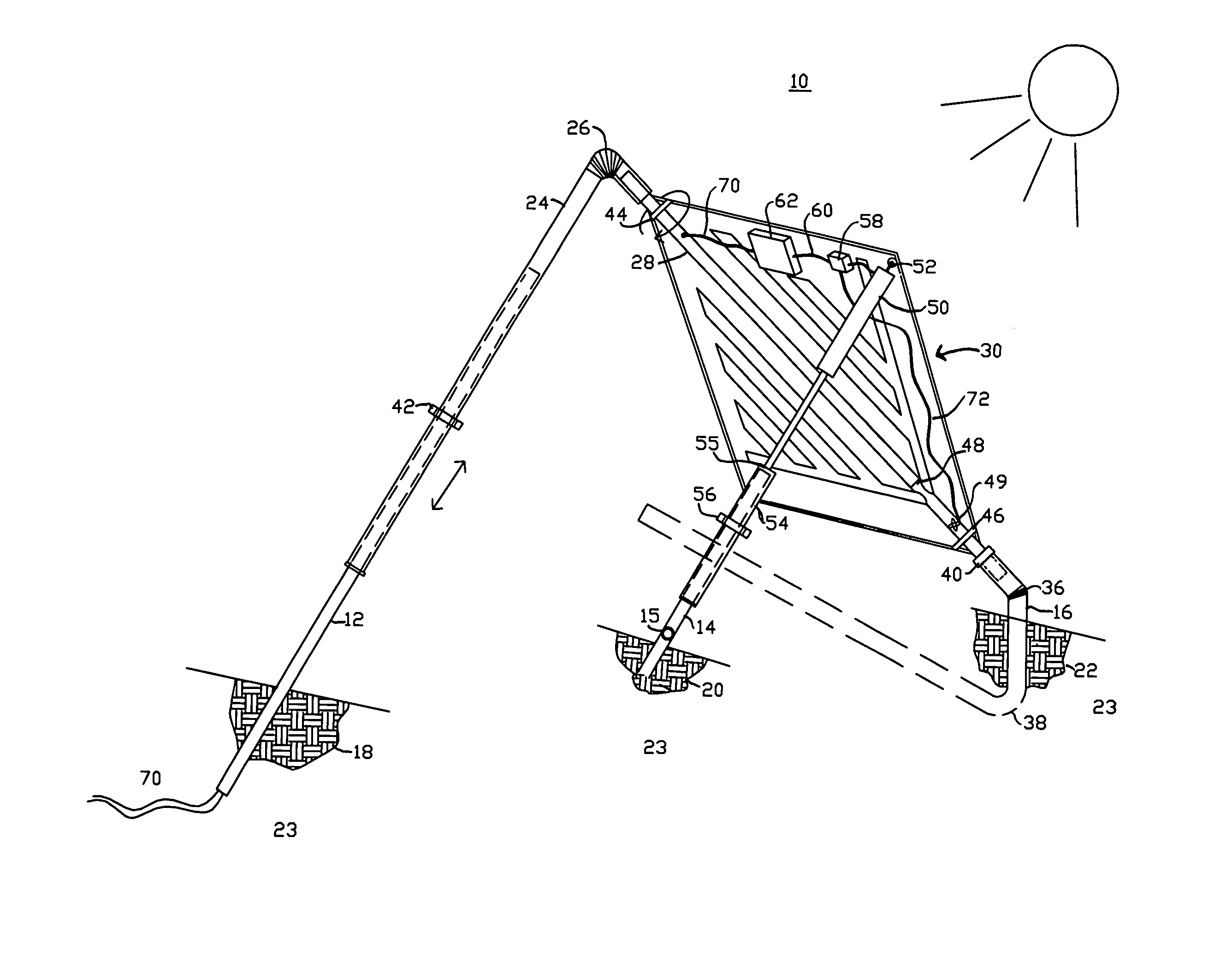
[0004] There is discovered a reliable and strong support structure that requires a minimum of electricity to realign panel(s), can withstand excessive winds, provides cooling to the solar panel(s), and contains additional benefits here summarized. The discovery of this invention is based upon the science of biomimicry, specifically the shape and behavior of a leaf. Leaves are often round, ovoid or tapered to a stem. Orientation of a solar panel is presented in which a corner of the panel is closest to the ground and connected to a hollow attachment member or pipe. The solar panel mimics the shape of a leaf when directly viewed. During rotation there is minimum interference of the panel with the ground surface, and greater sweep. Leaves maintain temperature, preventing desiccation, by drawing water upwards through the stem. Analogously, photovoltaic cells diminish in output and degrade under high temperatures. A source of cool air is generally available in the ground beneath a solar panel. Presented is a device to transfer cool ground air to the solar panel with zero or minimal input energy.
[0005] Solar panels to generate electricity are increasing in size. Today they are available at 315 Watt capacity, and larger, as a single complete unit. These panels are generally rectangular and approximately 4′2″ wide by 6′2″ long. The corner to corner diagonal length is approximately 7′4″ and weight is approximately 107 lbs. At some point, solar panel units may be of a circular, oval or triangular (isoceles or equilateral) shape in which this invention is equally suited. Most silicon type solar cells are constructed in a solar panel that is rectangular in shape. As silicon shortages affect the industry, various alternative shapes of panels will become available, because other materials are more conducive to different shaped panels. The support for panels is disclosed within this invention at a minimum but effective use of materials to meet structural considerations. The solar panel (or group) is supported along a balance line (polar axis) and a bracket provided at a free hanging corner of the solar panel and attached to a linear actuator. Whereas prior art arrangements provide a solar panel (or group) with the panel edge parallel with the ground or base, my disclosure shows the corner of a panel closest to the ground surface or base. The solar panel achieves the primary support coming from a member attached corner to corner. This provides several advantages. The panel can be positioned closer to the ground allowing rotation east to west with less ground interference at the extreme positions. The panel is less exposed to high winds. A separate frame is not required between the panel and the support member. The tubular support members can provide additional functions of a wire raceway and air conduit for cooling air. Stable third point support is provided with a linear actuator attached at the higher of the two free-hanging corners.
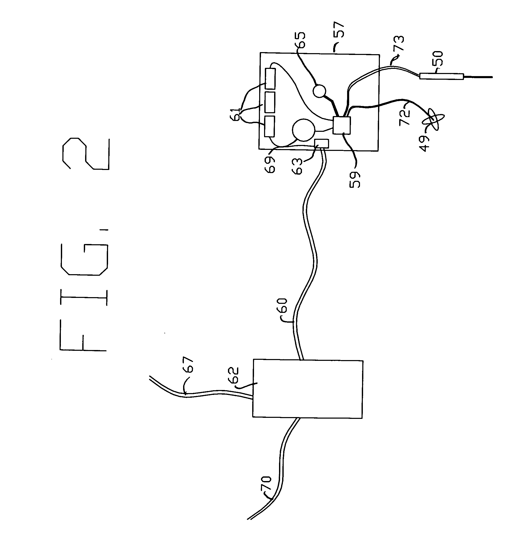
[0007] A cooling function consists of metal raceways or conduits attached to the back of a typical solar panel. These tubes are open at one end and join collectively near the bottom of the solar panel at a manifold. The manifold(s) interconnect with the hollow support member which is internally sealed to prevent air flow to the top of the solar panel. The air passageway is continuous through the lower post and into the ground where it is connected with an air infiltration gallery. The air infiltration gallery extends in the ground area directly beneath the solar panel. The air infiltration gallery includes one (or more) perforated pipe or chambers. To improve air flow capacity and heat capacity underground a zone of crushed rock or pea gravel is placed around the perforated pipe. As the solar panel heats up in summer days, the metal raceways will also heat up through conductive heat flow. This heats the air in the raceways causing a convective flow of air to occur. A vacuum is created drawing cool air from the air infiltration gallery up into the metal raceways and in turn cooling the solar panel. Alternatively a small fan may be installed in the hollow support member and controlled by the PLC. The fan may be activated to improve transfer of cool air to the solar panel during the heat of day. The electrical cost to operate the fan is exceeded by additional electrical generation from the photovoltaic panel at the now lower temperatures. At nighttime the fan may be reversed to pump cool air into the ground pore spaces. An additional feature is a fabric covering or rigid sheet about the support pipe closet to the pole; this provides additional shading to the ground surface under the solar panel in the early morning and late evening hours, as well as blocking wind to minimize wind uplift forces against a solar panel.

Problems solved by technology

Analogously, photovoltaic cells diminish in output and degrade under high temperatures.

Method used


Image

  • Device for supporting, aligning, and cooling a solar panel
  • Device for supporting, aligning, and cooling a solar panel
  • Device for supporting, aligning, and cooling a solar panel

Examples


Embodiment Construction

[0013] A solar panel support 10 shows embodiments as depicted in FIG. 1. Support members include pipes 12, 14, 16 anchored into concrete footings 18, 20, 22. Concrete footings 18, 20, 22 provide support to download dead and live loads and uplift forces transmitted by pipes 12, 14, 16. Pipe 12 and 16 extend through the concrete 18 and 22, respectively. Pipes 12, 14, 16 are rigidly constrained within concrete 18, 20, 22. Concrete 18, 20, 22 are contained by earth 23. Pipe 12 and Pipe 16 are arranged generally on a polar axis, Pipe 12 being closer to the pole. Pipe 14 includes a pivot linkage 15 providing a range of motion over a cone of approximately 30 degrees along the axis. An extension cover pipe 24 contains a flexible segment 26 and is sized for containment of attachment member 28. Attachment member 28 is generally a hollow pipe, however other shapes are embodied. Pipe 16 contains a flexible segment 36 as shown. Pipe 16 passes through concrete footing 22 and is attached to a buri...


PUM


Abstract

A device for solar panels and method allows seasonal tilting by human assistance for changes in sun angle above equator, and unassisted daily positioning east to west to east. A primary support member is fixed to the back of a typical solar panel, generally from corner to corner along a line of balance. This support member is elongated and enabled for rotation, with attached panel by rotation sleeves or pivots. Extensions of the rotation sleeves in connection with two posts are positioned on a polar axis. The posts are solidly fixed in the earth or a base. The rotation sleeve covering the longer post, closest to the pole, is manually adjusted and secured to change the angle of the collector with the equator. Stops are provided. A linear actuator is pivotally attached at an edge or corner of the solar panel with the other end attached to a post, which is pivotally attached relative to the ground or base. An electric motor is powered by batteries to drive the linear actuator. Control of the motor is regulated by programmed activation in response to time of day as maintained by an on board clock. The panel tracks the sun and at change of day returns to a preset position. Cooling of the solar panel is provided with subsurface air via infiltration gallery and distribution channels. Air moves by convection or with auxiliary fan.

Description

BACKGROUND OF THE INVENTION [0001] Solar collectors are known to have increased performance (heat or electricity) in cases where they can actively track the sun. Estimates of 30% or more power generation are estimated with active tracking solar devices over that of fixed mounting brackets. Tracking devices have typically taken the configuration of a single mast to support a collector or group of collectors such as U.S. Pat. No. 5,317,145 issued to Corio. Another configuration is shown by U.S. Pat. Nos. 6,253,632 and 6,089,224 issued to Poulek. In some cases adjustments of entire rows or groups of panels are suggested with a long interconnected rigid framework using a number of rods, cables or various mechanisms. See U.S. Pat. No. 6,302,099 to McDermott and U.S. Pat. No. 6,563,040 to Hayden et al. This prior art is generally expensive to manufacture, difficult to install, and inadequate against high winds such as encountered in Wyoming and other Rocky Mountain States. Additional refe...

Claims


Application Information

Patent Timeline
IPC IPC(8): F24J2/38F24S50/20
CPCF24J2/4638Y02E10/47F24J2002/5465F24J2/5264F24S40/85F24S2030/135F24S25/70
Inventor ROSE, ANDREW FERGUSON
Owner ROSE ANDREW FERGUSON
Learn More