Flow Rate Control Apparatus

a flow rate control and flow rate technology, applied in the direction of valve housings, functional valve types, transportation and packaging, etc., to achieve the effect of highly accurate control and stable operation

Inactive Publication Date: 2007-09-06
SMC CORP
View PDF5 Cites 54 Cited by
  • Summary
  • Abstract
  • Description
  • Claims
  • Application Information

AI Technical Summary

Benefits of technology

[0008]A general object of the present invention is to provide a flow rate control apparatus in which a flow passage-switching section and a pressure control section, for controlling the flow rate of a fluid that flows through passages thereof, are provided integrally with a base section composed of a stack, whereby the flow rate of the fluid can be controlled stably and highly accurately.

Problems solved by technology

Accordingly, unlike the conventional technique, it is unnecessary to perform specialized matching operations.

Method used


Image

  • Flow Rate Control Apparatus
  • Flow Rate Control Apparatus
  • Flow Rate Control Apparatus

Examples


first embodiment

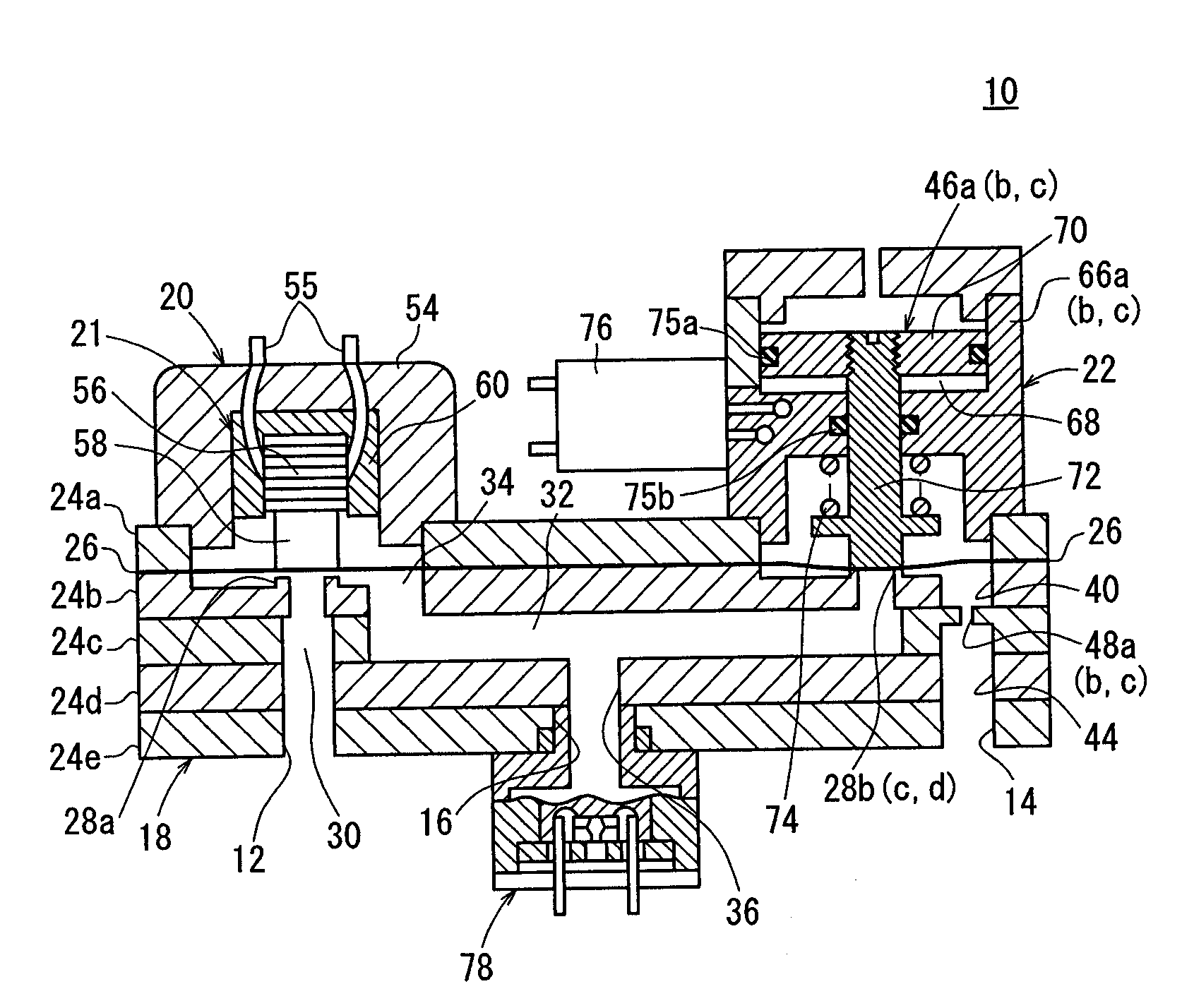
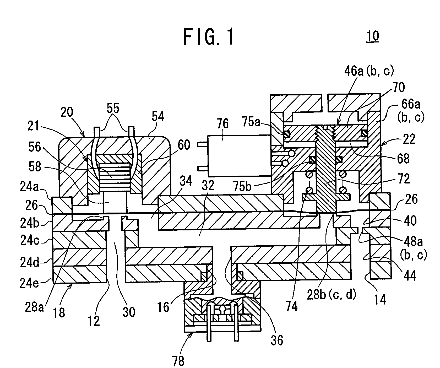
[0062]The flow rate control apparatus 10 according to the present invention is basically constructed as described above. Next, operations, functions and effects thereof shall be explained.

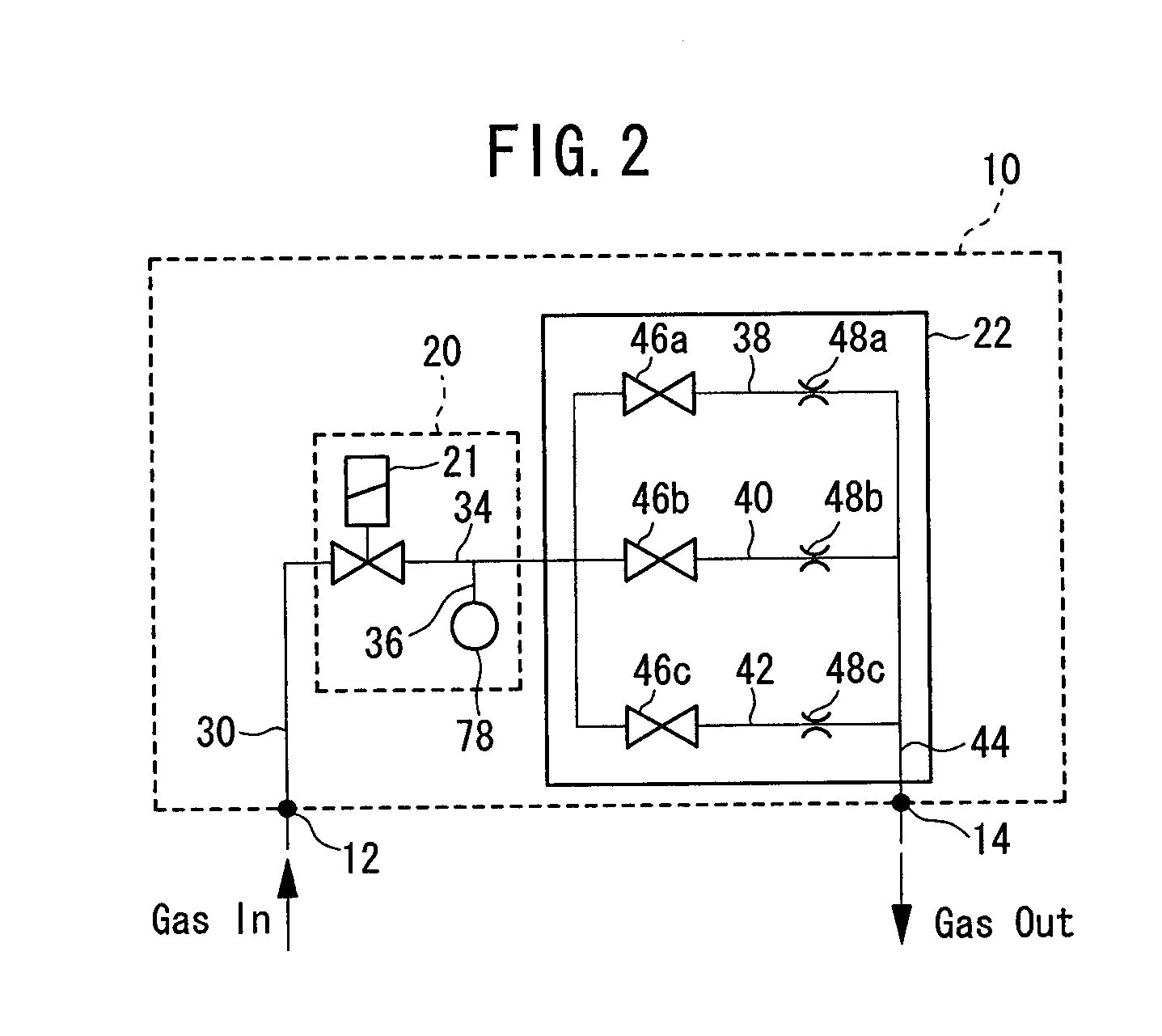
[0063]As shown in FIG. 10, the flow rate control apparatus 10 according to the first embodiment is arranged, for example, on the upstream side of a chamber 80 provided in a semiconductor manufacturing apparatus, and is used to supply gas at a predetermined flow rate into the chamber 80.

[0064]A gas supply source 82 is energized to introduce gas into the pressure control section 20 via the pressure fluid input port 12 and the first passage 30. In this situation, in the pressure control section 20, a predetermined voltage is applied to the piezoelectric / electrostrictive element 56 on the basis of a control signal derived from the unillustrated controller, in order to displace the piezoelectric / electrostrictive element 56 a predetermined length. Accordingly, the gap between the seat section 28a and the...

second embodiment

[0074]The flow rate control apparatus 100 shown in FIG. 14 is different from the apparatus of the foregoing embodiment in that a flow passage-switching control section 102 is arranged in place of the flow passage-switching section 22. The flow passage-switching control section 102 uses the linear solenoid valves 64 described above, for example, as control valves 21a to 21c in place of the first to third ON / OFF valves 46a to 46c. In addition, other pressure sensors 78a to 78c are provided between the linear solenoid valves 64 and the first to third orifices 48a to 48c respectively.

[0075]In this arrangement, the other pressure sensors 78a to 78c are provided at lower portions of the stacked base section 18 in order to sense the pressure of the gas introduced via unillustrated passages disposed in the vertical direction and which communicate with the fourth to sixth passages 38, 40, 42 respectively. A predetermined flow rate is established on the basis of detection signals correspondi...


PUM


Abstract

A flow rate control apparatus includes a base section, wherein the base section is composed of a plurality of stacked metal plates. The flow rate control apparatus further includes a pressure control section, which regulates pressure of a pressure fluid (gas) that flows through a first passage in the base section, a pressure sensor that detects pressure of the pressure fluid flowing through a second passage, and a flow passage-switching section, including first to third orifices, for throttling the fluid pressure-regulated by the pressure control section so as to have a predetermined flow rate, and which has first to third ON/OFF valves for switching fourth to sixth passages for respectively directing the pressure fluid toward a pressure fluid output port.

Description

BACKGROUND OF THE INVENTION[0001]1. Field of the Invention[0002]The present invention relates to a flow rate control apparatus, which is capable of obtaining a stable output by highly accurately controlling the flow rate of a pressure fluid.[0003]2. Description of the Related Art[0004]For example, Japanese Laid-Open Patent Publication No. 8-35506 discloses a fluid control unit constructed by stacking a plurality of metal plates, which have flow passages composed of penetrating holes and non-penetrating holes formed perpendicularly with respect to surfaces of the metal plates.[0005]In the case of this fluid control unit, fluid interference areas and flow passages, which are composed of the penetrating and non-penetrating holes, are formed by press working the plurality of metal plates. Further, after respective surfaces of the plates have been processed with grinding grains, the respective metal plates are stacked and joined by means of diffusion joining or brazing joining. According...

Claims


Application Information

Patent Timeline
Patent Type & Authority Applications(United States)
IPC IPC(8): F16K47/00F16K15/00B05B1/14
CPCF15B13/081F15B13/0814F15B13/0835F15B13/0857F16K27/029F15B13/0889F15B13/0896F16K11/22F16K27/0263F15B13/086Y10T137/7722F15C5/00F15C7/00
Inventor KUROSAWA, KENICHI
Owner SMC CORP
Why Eureka
Try Eureka