Apparatus for transferring torque magnetically

a magnetic transfer and torque technology, applied in magnetically actuated clutches, asynchronous induction clutches/brakes, electrostatic holding devices, etc., can solve the problems of eddy current devices, limited torque transmission ability of current fixed gap permanent magnet disk clutches, and instability at higher speeds

Inactive Publication Date: 2007-09-06
OSERAN WILLIAM A +1
View PDF8 Cites 12 Cited by
  • Summary
  • Abstract
  • Description
  • Claims
  • Application Information

AI Technical Summary

Benefits of technology

[0012] The present invention utilizes permanent magnets to transmit variable or fixed torque between two rotating elements. In one embodiment, the torque between the elements may be adjusted by mechanically varying the amount of magnetic flux passing between the elements. This is accomplished by varying the extent to which the elements are axially overlapped. In a preferred embodiment of the apparatus, two concentric cylinders, one containing one or more rows of permanent magnets, is moved axially in order to progressively axially overlap a second cylindrical element containing electrically conductive and magnetically conductive elements. This progressive axial overlapping of the two cylinders allows variation in the amount of magnetic flux intersecting the two concentric cylinders. This causes the amount of induced electrical current in the cylinder containing the electro-conductive elements to vary, which then causes the induced counter magnetic forces to vary. The magnetic forces and, thus, torque transmitted will vary based on the amount of axial overlap.
[0013] The proposed invention overcomes previous limitations by taking advantage of new technologies in magnet materials and provides a stable means of mechanically varying large amounts of transmitted torque without the need for large external current controls.

Problems solved by technology

An examination of the prior art shows that these eddy current devices are limited to three general types 1.
Current fixed gap permanent magnet disk clutches are limited in their ability to transmit large amounts of torque and are constructed in a manner which causes instability at higher speeds.
These limitations relegate the practical application of these devices to low speed, low horsepower application.
These devices are available in a wide range of horse power but are expensive, complicated and require a DC current and control to induce the torque.
There are applications where the DC current is not desirable or where the apparatus for controlling the torque producing currents are unreliable.
Current variable gap permanent magnet disk clutches are limited in their ability to transmit large amounts of torque and are constructed in a manner which causes instability at higher speeds.
These limitations relegate the practical application of these devices to low speed, low horsepower application.

Method used


Image

  • Apparatus for transferring torque magnetically
  • Apparatus for transferring torque magnetically
  • Apparatus for transferring torque magnetically

Examples


first embodiment

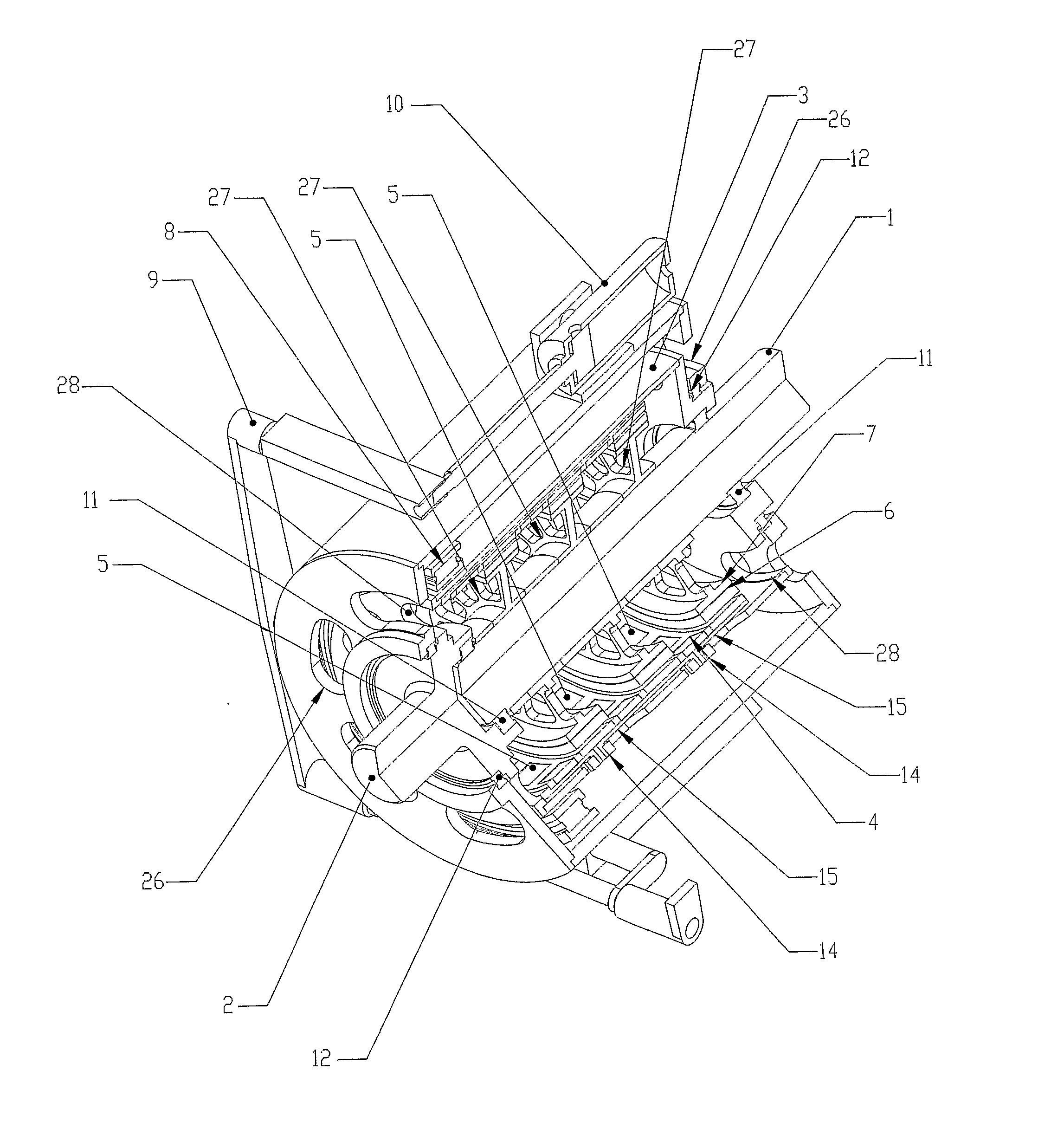
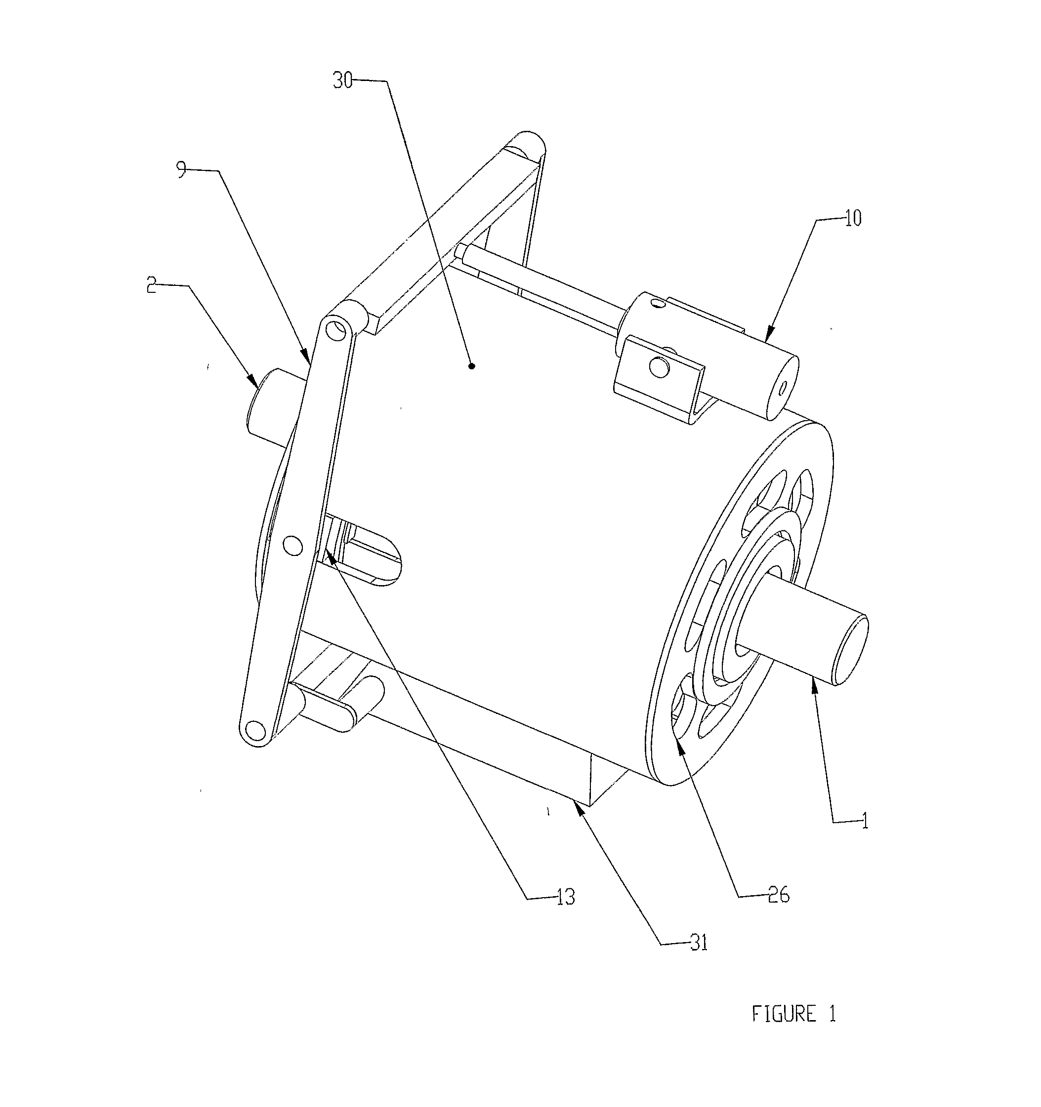
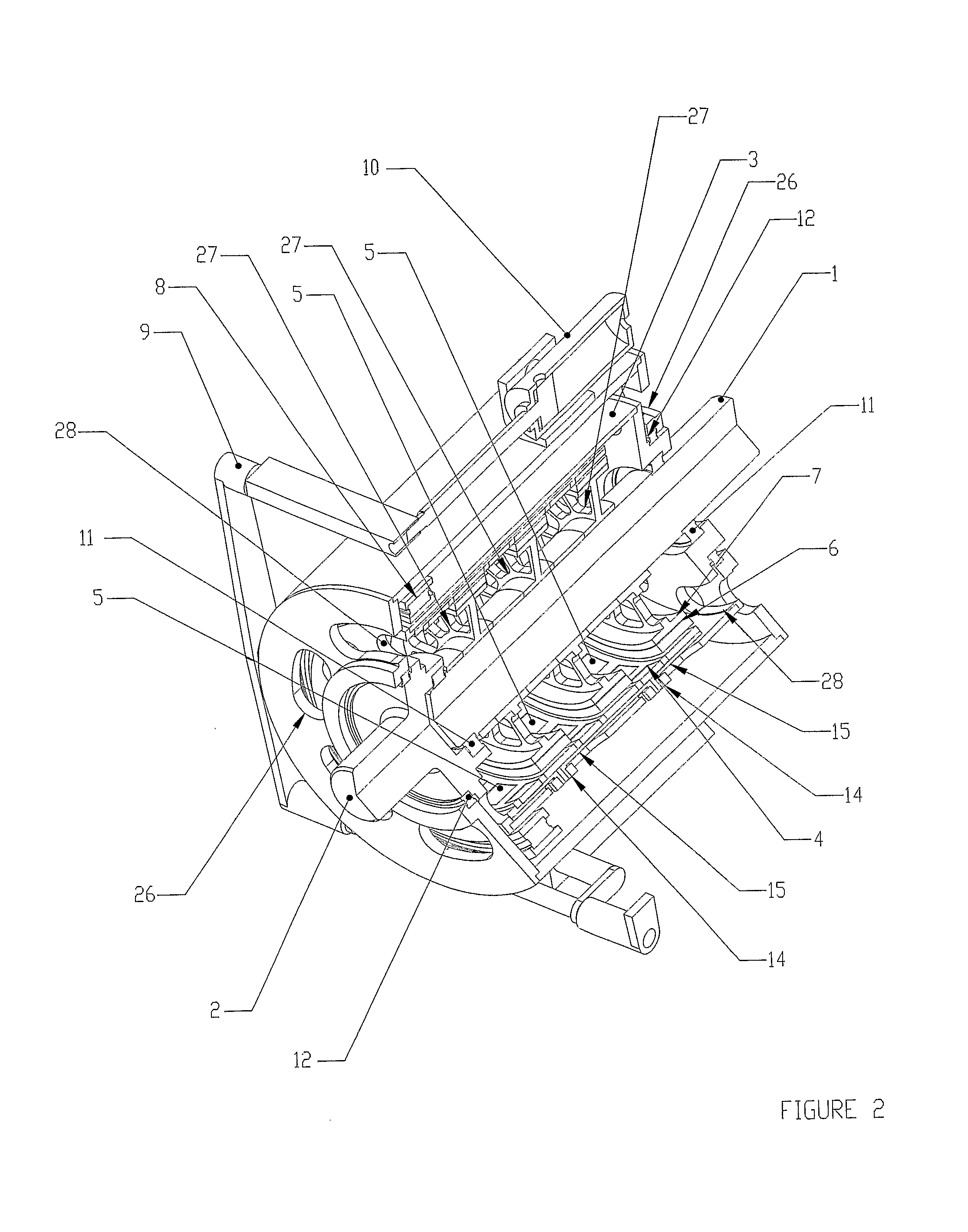
[0026] Referring to FIGS. 1 through 4, the invention is shown and described as it applies to a variable speed drive application. The first part of the variable speed torque transfer apparatus described in this preferred embodiment consists of a primary rotary member comprising an input shaft rotor (2), a support cylinder (3), and a magnet-carrying rotor (4), all mechanically connected together, and constrained to rotate at the same angular velocity together. The second part of the variable speed torque transfer apparatus described in this preferred embodiment consists of a secondary rotary member comprising an output shaft rotor (1), magnetically permeable ferrous wheels (7) which support and back the electro-conductive rings (6), all mechanically connected together, and constrained to rotate at the same angular velocity together. The input shaft (2) is connected directly to a concentric support cylinder (3), which is constrained to rotate with the input shaft (2). The support cylin...

third embodiment

[0035] A second alternative embodiment, or third embodiment, is depicted in FIGS. 8 and 9. In this second alternative embodiment, the relative axial position of the two co-axial cylinders remains fixed at what ever axial position the end user desires. This is a mechanically simpler embodiment than the previously described embodiments, and is used in services that do not require the output rotating shaft's angular velocity to vary appreciably from the input rotating shaft's angular velocity while operating. Yet, all the other advantages of the preferred embodiment remain; i.e., relaxed alignment requirements, less shaft-to-shaft vibration transmission, etc. The first part of this torque transfer apparatus described in this second alternative embodiment consists of a primary rotary member comprising an input shaft rotor (218) and a magnet-carrying rotor (220), mechanically connected together, and constrained to rotate at the same angular velocity together. The second part of this torq...


PUM


Abstract

An apparatus for transferring torque magnetically with a primary rotary member and a secondary rotary member. The primary rotary member has permanent magnets mounted circumferentially on a cylinder, the secondary rotary member having a cylindrical geometry with electroconductive material arranged on its outer periphery and parallel to the axes of the rotary members. The secondary rotary member also having magnetically permeable material. The secondary rotary member is placed partially or totally inside the primary rotating member. The secondary rotary member's axial position relative to the primary rotating member can be varied by a suitable mechanical structure. This causes the two rotary members to axially overlap one another more or less as desired. Rotation of the primary rotary member causes rotation of the secondary rotary member, since magnetic flux lines emanating from the permanent magnets mounted on the primary rotating member, cut through all, or part of, the electroconductive material placed on the periphery of the secondary rotary member. This can vary the torque transmitted between the two rotary members, thereby enabling the varying of the rotational speed of the secondary rotary member relative to the primary rotary member.

Description

CROSS REFERENCE TO RELATED APPLICATIONS [0001] This PCT international application claims priority from current pending U.S. patent application Ser. No. 10 / 790,571 which has a priority filing date of Mar. 1, 2004.STATEMENT REGARDING U.S. FEDERALLY SPONSORED RESEARCH OR DEVELOPMENT [0002] Not Applicable. DESCRIPTION OF ATTACHED APPENDIX [0003] Not Applicable. TECHNICAL FIELD OF THE INVENTION [0004] The present invention relates to rotational magnetic torque transfer devices utilizing two coaxial cylinders overlapping one another wherein one cylinder contains a row(s) of permanent magnets and the other cylinder contains a ring(s) of electroconductive material. BACKGROUND OF THE INVENTION [0005] It is desirable to devise a permanent magnet excited mechanism for transmitting variable torque in drive applications. Specifically there is a need to couple constant speed devices such as motors or engines to variable output speed and torque devices such as pump impellers, fans, propellers, whe...

Claims


Application Information

Patent Timeline
Patent Type & Authority Applications(United States)
IPC IPC(8): F16D27/00H02K49/00H02K49/02H02K49/10H02K51/00
CPCH02K49/02Y10T464/30H02K51/00H02K49/106
Inventor CORBIN, PHILIP III
Owner OSERAN WILLIAM A
Why Eureka
Try Eureka