Patch antenna with comb substrate

a patch antenna and substrate technology, applied in the field of patch antennas, can solve the problems of undesirable increase in antenna weight and increase in thickness, and achieve the effects of reducing the speed of a wave traveling across the structure, reducing the size and weight of patch antennas, and increasing the angular response pattern of patch antennas

Active Publication Date: 2007-09-06
TOPCON GPS
View PDF16 Cites 23 Cited by
  • Summary
  • Abstract
  • Description
  • Claims
  • Application Information

AI Technical Summary

Benefits of technology

[0007] The present inventors have recognized that it would be desirable in many implementations to reduce the size and weight of patch antennas and, at the same time, to increase the angular response pattern of a patch antenna. The present invention substantially achieves these objectives. In particular, the present invention is a patch antenna having a plurality of structures, referred to herein as comb structures, that are attached to the ground plane and / or the patch of the antenna. These comb structures are illustratively made of conductive materials (e.g., metals or dielectric painted by conductive paint). However, by using such a plurality of combs, the speed of a wave traveling across the structures is significantly reduced. Hence, such combs structures operate similarly to a dielectric and, therefore, could be characterized by effective dielectric constant εeff. The use of such comb structures serves to reduce the overall patch size (e.g., length and width) and to broaden the angular response pattern of the antenna.

Problems solved by technology

However, such an increase in thickness will also undesirably increase the weight of the antenna.

Method used


Image

  • Patch antenna with comb substrate
  • Patch antenna with comb substrate
  • Patch antenna with comb substrate

Examples


Embodiment Construction

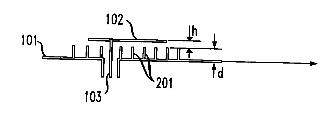
[0017] As discussed above, the angular response pattern of an antenna can be broadened by decreasing the length of a patch. To obtain this broadening for a given operating frequency of a patch antenna the εeff of a substrate should be increased. This in turn results in narrowing the operating frequency band. To keep the operating frequency bandwidth at the desired value the thickness of the substrate should be increased to separate the patch from the ground plane by a greater distance. However, such an increase in thickness will have the detrimental effect of increasing the weight of the antenna. It would be desirable to maintain a constant εeff of a substrate and length of a patch in an antenna while, at the same time, separating the ground plane from the patch.

[0018] The present invention substantially achieves this objective. FIGS. 2A and 2B show one illustrative embodiment of a patch antenna in accordance with the principles of the present invention whereby the angular response...


PUM


Abstract

A patch antenna having a plurality of structures, referred to herein as comb structures, is disclosed that results in an antenna having a reduced overall patch size and weight as well as a broader the angular response pattern of the antenna. In a first embodiment, comb structures are attached to one of the surface of the patch or the surface of the ground plane. In a second embodiment, the comb structures are attached to both the patch and the ground plane in a manner such that the structures interleave with each other. The structures may be pins or ribs that are electrically connected to the ground plane and/or the patch, or may be any other suitable configuration depending upon the polarization of the signal to be transmitted or received.

Description

[0001] This application claims the benefit of U.S. Provisional Application No. 60 / 644,948, filed Jan. 19, 2005, which is hereby incorporated herein by reference.BACKGROUND OF THE INVENTION [0002] The present invention relates to antennas and, more particularly, to patch antennas. [0003] Patch antennas, which are typically characterized by a flat radiating element placed in close proximity to a ground plane, are used for many beneficial purposes, such as for individual elements in phased array antennas. Such patch antennas are gaining in popularity due, in part, to their relatively small size and relatively low production cost as compared to other types of antennas. The various uses of patch antennas are well known and will not be discussed further herein. [0004] Patch antennas typically consist of a radiating patch separated from a ground plane by a dielectric substrate. Referring to FIG. 1, for example, a patch antenna in a typical prior implementation consists of a ground plane 10...

Claims


Application Information

Patent Timeline
Patent Type & Authority Applications(United States)
IPC IPC(8): H01Q1/38
CPCH01Q1/38H01Q15/0073H01Q9/0407
Inventor TATARNIKOV, DMITRY V.ASTAKHOV, ANDREY V.SHAMATULSKY, PAVEL P.SOUTIAGUINE, IGOR V.STEPANENKO, ANTON P.
Owner TOPCON GPS
Why Eureka
Try Eureka