RFID reader with adaptive carrier cancellation

a technology of adaptive carrier cancellation and rfid reader, which is applied in the direction of instruments, mechanical actuation of burglar alarms, pulse techniques, etc., can solve the problems of significant noise to the received signal, noise and interference with the received signal, and particularly cost-effective transponders that extract their power from the interrogating electromagnetic field

Inactive Publication Date: 2007-09-06
APPLIED WIRELESS IDENTIFICATIONS GROUP
View PDF33 Cites 37 Cited by
  • Summary
  • Abstract
  • Description
  • Claims
  • Application Information

AI Technical Summary

Benefits of technology

[0012] A method for processing an RF signal according to another embodiment of the present invention includes receiving an incoming signal, separating the incoming signal into I and Q components, extracting higher frequency signals from the I and Q components, extracting data from the higher frequency signals, extracting lower frequency signals from the I and Q components,

Problems solved by technology

RFID transponders that extract their power from the interrogating electromagnetic field are particularly cost effective since they lack a power source.
As a result of the simultaneous carrier transmision and receive function, a portion of the transmitted signal can leak into the received signal path, providing a significant source of noise to the received signal.
Moreover, there may only

Method used


Image

  • RFID reader with adaptive carrier cancellation
  • RFID reader with adaptive carrier cancellation
  • RFID reader with adaptive carrier cancellation

Examples


Embodiment Construction

[0026] The following description is the best mode presently contemplated for carrying out the present invention. This description is made for the purpose of illustrating the general principles of the present invention and is not meant to limit the inventive concepts claimed herein. Further, particular features described herein can be used in combination with other described features in each of the various possible combinations and permutations.

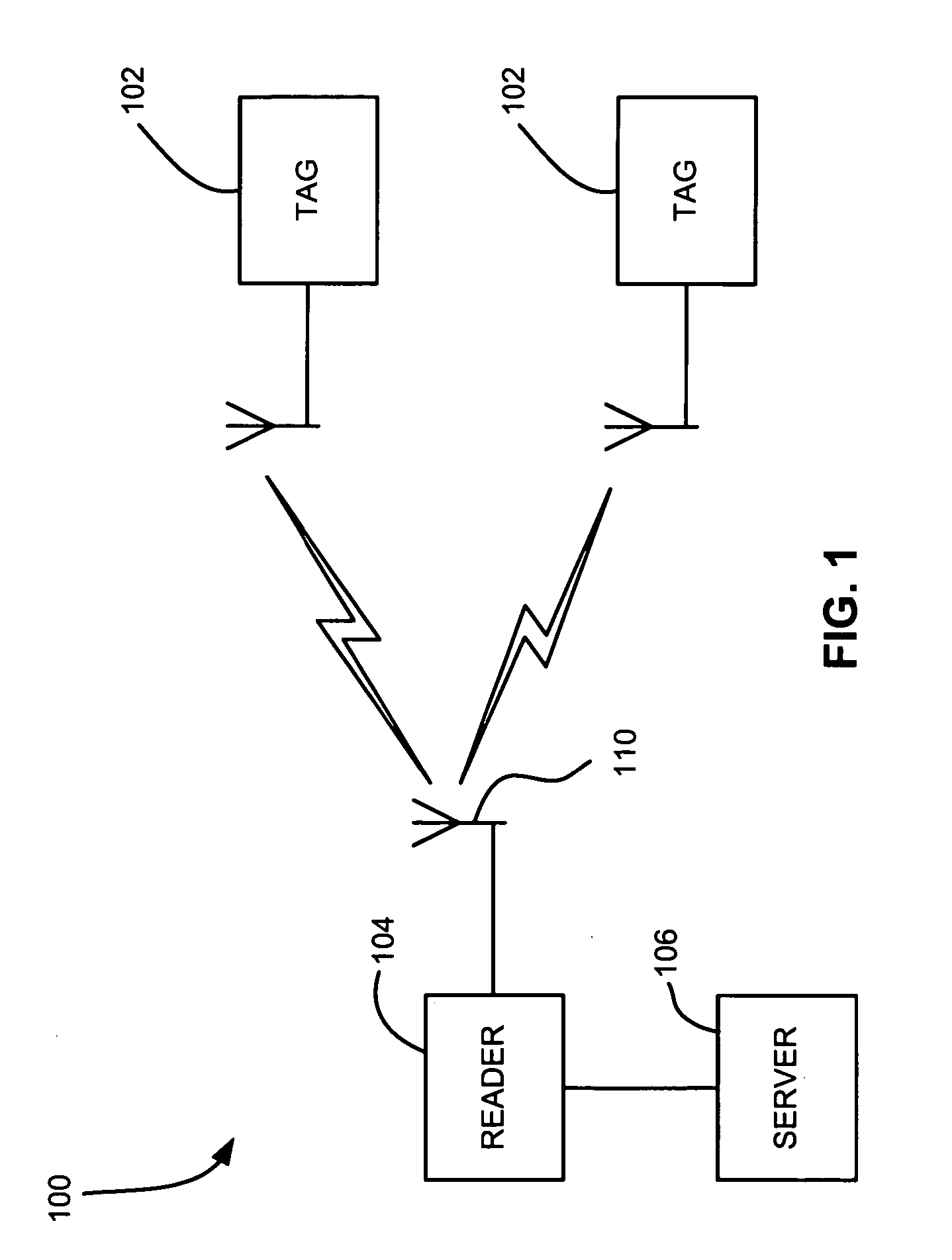
[0027] The use of RFID tags are quickly gaining popularity for use in the monitoring and tracking of an item. RFID technology allows a user to remotely store and retrieve data in connection with an item utilizing a small, unobtrusive tag. As an RFID tag operates in the radio frequency (RF) portion of the electromagnetic spectrum, an electromagnetic or electrostatic coupling can occur between an RFID tag affixed to an item and an RFID tag reader. This coupling is advantageous, as it precludes the need for a direct contact or line of sight conn...


PUM


Abstract

An RFID reader includes first and second mixers receiving an incoming signal, circuitry for adding a portion of an outgoing signal to an incoming signal, first and second analog feedback loops coupling outputs of the first and second mixers to the circuitry for adding the outgoing signal to the incoming signal. An amount of outgoing signal added to the incoming signal depends on signals in the feedback loops. An RFID reader in another embodiment of the present invention includes a first mixer receiving an incoming signal, a second mixer receiving the incoming signal, an AC-coupled section coupled to the mixer outputs, and a DC-coupled section coupled to the mixer outputs. An RFID reader in another embodiment of the present invention includes an analog loop for adaptive carrier signal cancellation from an incoming signal, and a digital loop for controlling a gain of the incoming signal. Methods are also presented.

Description

FIELD OF THE INVENTION [0001] The present invention relates to Radio Frequency Identification (RFID) readers, and more particularly, this invention relates to a new RFID reader architecture. BACKGROUND OF THE INVENTION [0002] RFID technology employs a radio frequency (“RF”) wireless link and ultra-small embedded computer circuitry on an RFID tag. RFID technology allows physical objects to be identified and tracked via these wireless “tags”. It functions like a bar code that communicates to the reader automatically, but without requiring manual line-of-sight scanning or singulation of the objects. RFID promises to radically transform the retail, pharmaceutical, military, transportation, and other industries. [0003] In the automatic data identification industry, the use of RFID transponders (also known as RFID tags) has grown in prominence as a way to track data regarding an object to which the RFID transponder is affixed. An RFID transponder generally includes a semiconductor memory ...

Claims


Application Information

Patent Timeline
IPC IPC(8): H04L27/00G08B13/14H04Q5/22G06F3/033
CPCG06K7/0008G06K7/10029H04B1/59G06K7/10217G06K7/10079
Inventor ZHOU, LIMINGSTEWART, ROGER GREEN
Owner APPLIED WIRELESS IDENTIFICATIONS GROUP
Why Eureka
Try Eureka