Fuel cell

a fuel cell and cell technology, applied in the field of fuel cells, can solve problems such as turbulence in the reactant gas flow, and achieve the effects of convenient gas humidification, convenient use, and convenient us

Inactive Publication Date: 2007-09-06
HONDA MOTOR CO LTD
View PDF6 Cites 13 Cited by
  • Summary
  • Abstract
  • Description
  • Claims
  • Application Information

AI Technical Summary

Benefits of technology

[0011]A main object of the present invention is to provide a fuel cell having a compact structure, in which it is possible to achieve a desired water vapor permeability, and wherein efficient gas humidification can be performed suitably.

Problems solved by technology

Therefore, the gas flow rate of gas flowing along the outer surface of the humidification section is increased, resulting in turbulence that occurs in the reactant gas flow.

Method used


Image

  • Fuel cell
  • Fuel cell
  • Fuel cell

Examples


first embodiment

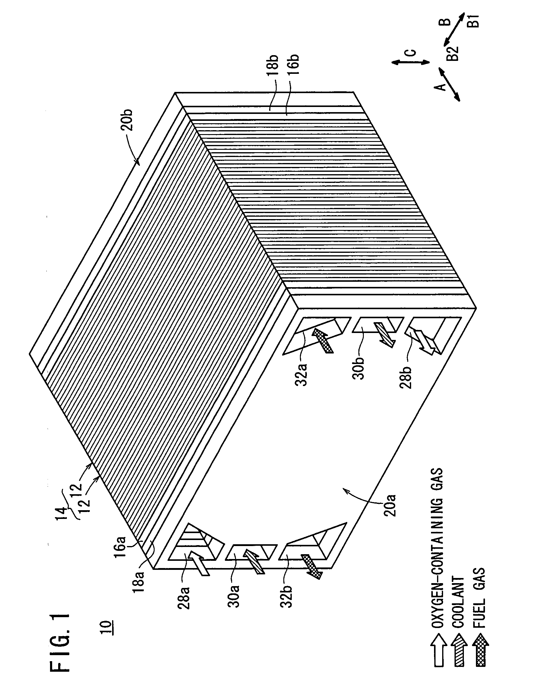
[0028]FIG. 1 is a perspective view showing a fuel cell stack 10 according to the present invention.

[0029]The fuel cell stack 10 includes a stack body 14 formed by stacking a plurality of power generation cells 12 in a substantially horizontal direction, as indicated by the arrow A. Terminal plates 16a, 16b are provided at opposite ends of the stack body 14 in the stacking direction. Insulating plates 18a, 18b are disposed outside of the terminal plates 16a, 16b, and end plates 20a, 20b are disposed outside of the insulating plates 18a, 18b. The components disposed between the end plates 20a and 20b are tightened by means of tightening bolts (not shown) in the stacking direction. Alternatively, the stack body 14 may be arranged within a box-shaped casing (not shown). Typically, the fuel cell stack 10 is mounted in a vehicle such as an automobile, for example.

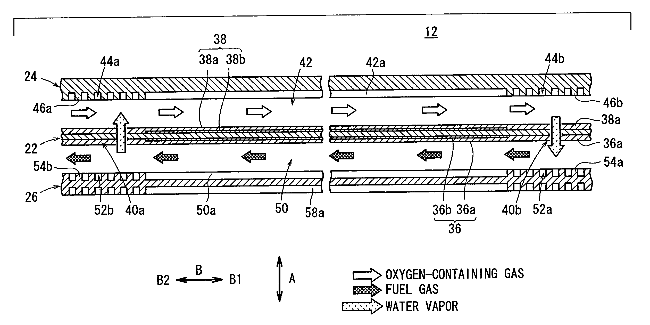
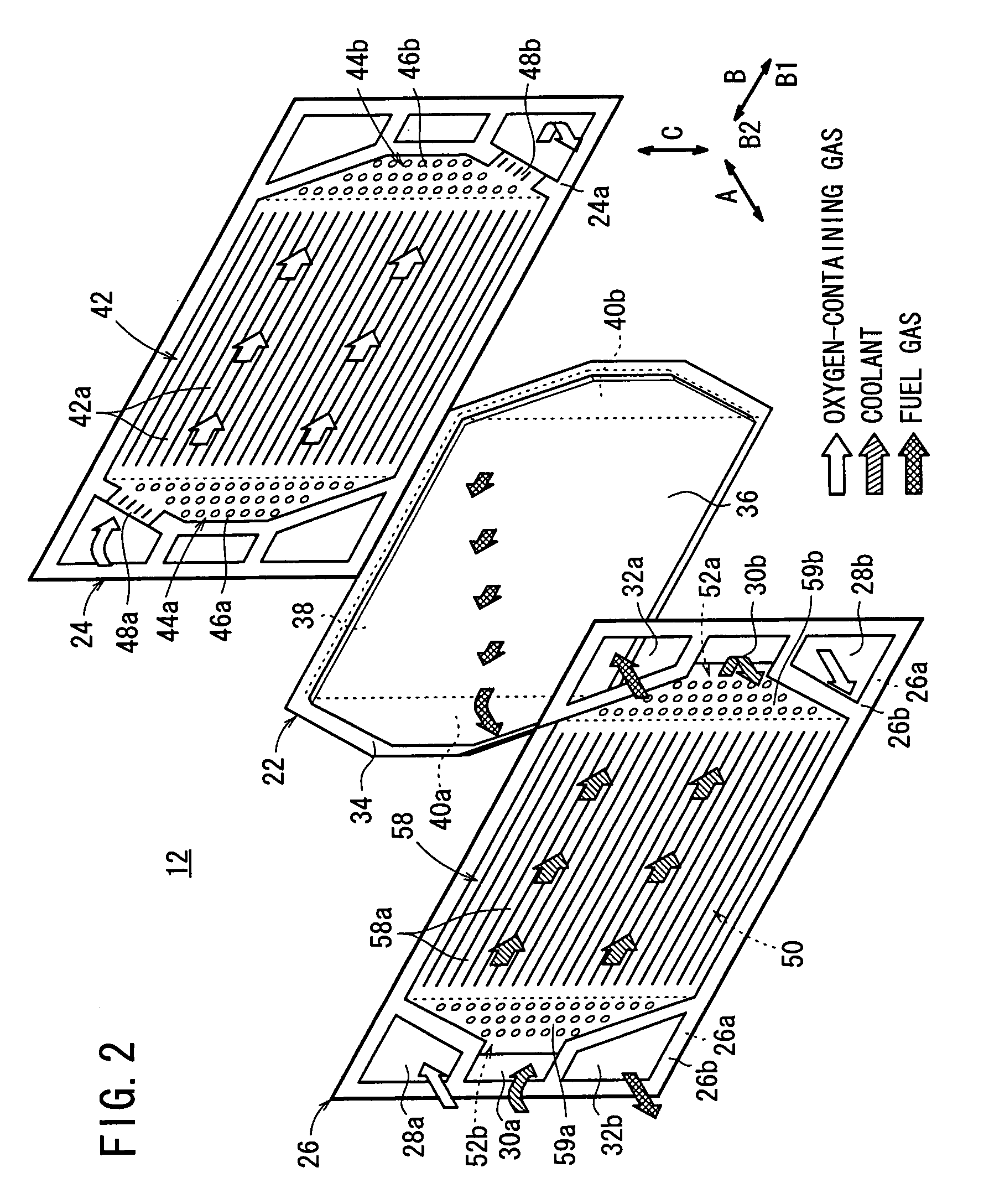
[0030]As shown in FIGS. 2 and 3, each of the power generation cells 12 includes a membrane electrode assembly 22, and first and...

second embodiment

[0066]In the second embodiment, the first and second separators 74, 76 can be formed by metal plates. The first and second cylindrical protrusions 80a, 80b can be fabricated by pressure forming. Thus, the structure of the first and second separators 74, 76 is simplified significantly, and overall production costs for the fuel cell stack are reduced.

third embodiment

[0067]FIG. 7 is a partial enlarged view showing a first separator 92 of a power generation cell 90 of a fuel cell stack according to the present invention. FIG. 8 is a partial cross sectional view showing the power generation cell 90 of FIG. 7.

[0068]The first separator 92 is a carbon plate. A plurality of pyramid shaped resistance members 94 are formed within an outlet buffer area 44b of the first separator 92, providing resistance to the flow of the oxygen-containing gas. Each of the pyramid shaped resistance members 94 has an inclined surface 94a, which is tapered (narrowed) toward the membrane electrode assembly 22. A top surface 94b of the pyramid shaped resistance member 94, having the smallest cross sectional area, contacts the second humidification section 40b.


PUM

PropertyMeasurementUnit
areaaaaaaaaaaa
resistanceaaaaaaaaaa
prismatic resistanceaaaaaaaaaa

Abstract

A power generation cell includes a membrane electrode assembly, and first and second separators sandwiching the membrane electrode assembly. The first separator includes an oxygen-containing gas flow field. An inlet buffer area is provided between the oxygen-containing gas flow field and an oxygen-containing gas supply passage, and an outlet buffer area is provided between the oxygen-containing gas flow field and an oxygen-containing gas discharge passage. Plural columnar resistance members are provided within the inlet buffer area and the outlet buffer area. The membrane electrode assembly further includes first and second humidification sections.

Description

BACKGROUND OF THE INVENTION[0001]1. Field of the Invention[0002]The present invention relates to a fuel cell formed by stacking a membrane electrode assembly and a separator in a stacking direction. The membrane electrode assembly includes a pair of electrodes and an electrolyte membrane interposed between the electrodes. A reactant gas passage acting as a passage for a reactant gas extends through the separator in the stacking direction.[0003]2. Description of the Related Art[0004]A polymer electrolyte fuel cell employs a membrane electrode assembly (MEA), which includes an anode, a cathode, and an electrolyte membrane interposed between the anode and the cathode. The electrolyte membrane is a solid polymer ion exchange membrane. The membrane electrode assembly and separators sandwiching the membrane electrode assembly make up a unit of a power generation cell for generating electricity. Normally, a predetermined number of power generation cells are stacked together, wherein termin...

Claims


Application Information

Patent Timeline
Patent Type & Authority Applications(United States)
IPC IPC(8): H01M8/02H01M8/10H01M4/94
CPCH01M8/0256H01M8/04141Y02E60/50H01M8/241H01M2008/1095H01M8/04149H01M8/2483H01M8/0258
Inventor USHIO, TAKESHIIWASAWA, CHIKARA
Owner HONDA MOTOR CO LTD
Why Eureka
Try Eureka