
Solid oxide fuel cell cathode material

a fuel cell and solid oxide technology, applied in the direction of cell components, basic electric elements, electrochemical generators, etc., can solve the problems of increased in-plane resistance, lower efficiency, and higher polarization, and achieve lower interfacial resistance, lower cost, and higher oxygen ion conductivity

Inactive Publication Date: 2007-09-06
UT BATTELLE LLC
View PDF3 Cites 2 Cited by
  • Summary
  • Abstract
  • Description
  • Claims
  • Application Information

AI Technical Summary

Benefits of technology

[0009] Accordingly, objects of the present invention include provision of SOFC cathode material compositions at a potentially lower cost (because inexpensive, readily available materials are used in the composition), higher oxygen ion conductivity, and lower interfacial resistance under operating conditions. Further and other objects of the present invention will become apparent from the description contained herein. SUMMARY OF THE INVENTION

Problems solved by technology

However, higher surface area cathodes tend to lead to increased in-plane resistance, higher polarization, and lower efficiency.
At least one negative issue known to be associated with the use of the above-described materials is that they react with the zirconia electrolyte, forming unwanted insulating phases.
Several other issues are the cost of La and that the oxygen ion conductivity is limited to less than 10% of the total conductivity.

Method used


Image

  • Solid oxide fuel cell cathode material
  • Solid oxide fuel cell cathode material
  • Solid oxide fuel cell cathode material

Examples


example i

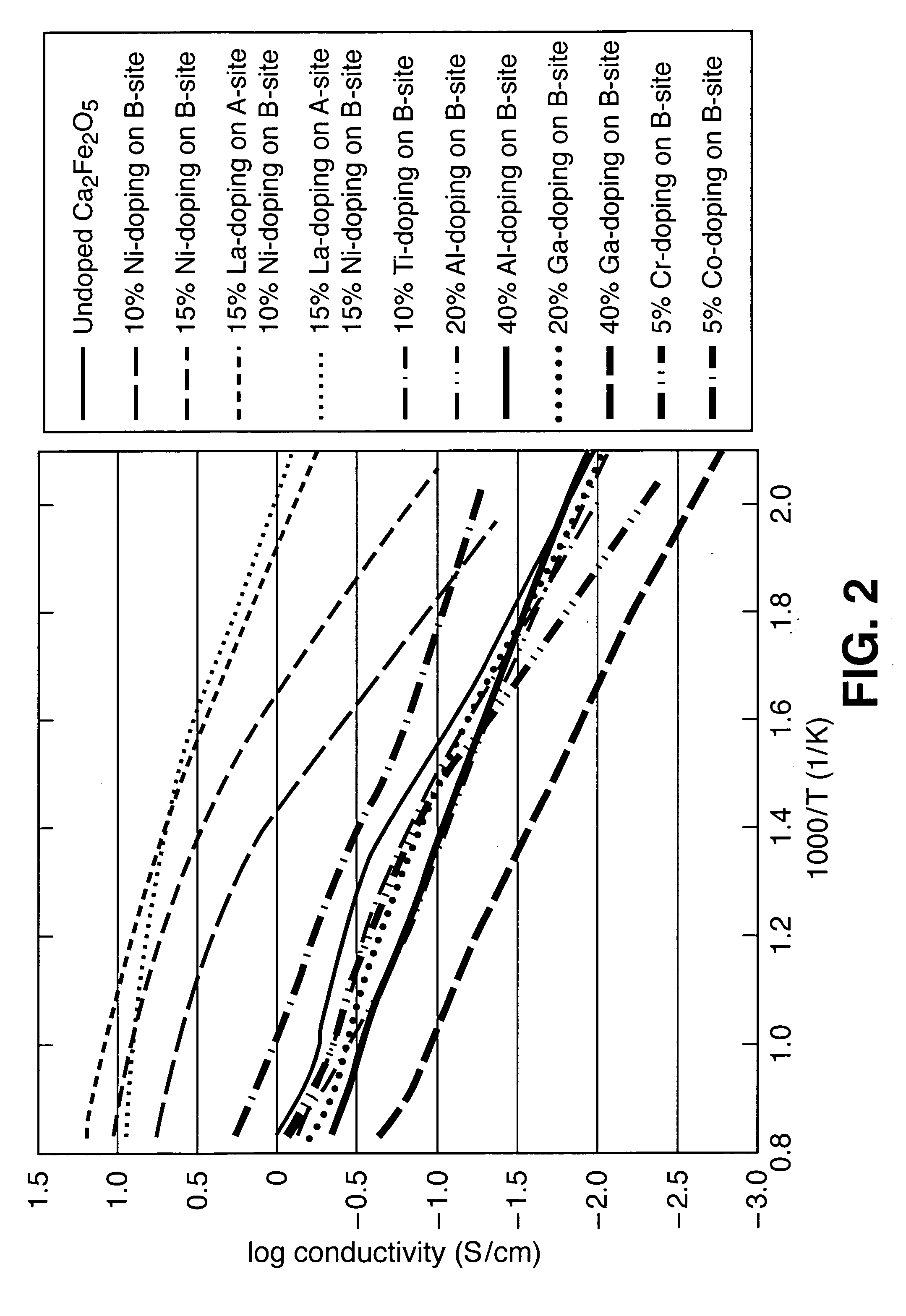
[0029] Total conductivity of (Ca2-xAx)(Fe2-yBy)O5±d was altered by A- and B-site doping of various samples: [0030] 10% Ni doping on the B-site [0031] 15% Ni doping on the B-site [0032] 15% La doping on the B-site and 10% Ni doping on the B-site [0033] 15% La doping on the B-site and 15% Ni doping on the B-site [0034] 10% Ti doping on the B-site [0035] 20% Al doping on the B-site [0036] 50% Al doping on the B-site [0037] 20% Ga doping on the B-site [0038] 40% Ga doping on the B-site [0039] 5% Cr doping on the B-site [0040] 5% Co doping on the B-site [0041]FIG. 2 contains Arrhenius plots of total conductivity in air for undoped Ca2Fe2O5 and the above-listed compositions.

[0042]FIG. 2 shows that the conductivity at 900° C. varies by 2 orders of magnitude depending on the doping scheme; the conductivity at 300° C. varies by almost 3 orders of magnitude depending on the doping scheme. Doping not only changes the overall conductivity, but also changes the contribution of different conduct...

example ii

[0043] Total conductivity of (Ca2-xAx)(Fe2-yBy)O5±d was altered by A- and B-site doping of various samples and tested dry H2 and humidified (wet) H2: [0044] 10% Ti-doping on the B-site, in wet H2 [0045] 10% Ti-doping on the B-site, in dry H2 [0046] 20% Al-doping on the B-site, in wet H2 [0047] 20% Al-doping on the B-site, in dry H2 [0048] 40% Al-doping on the B-site, in wet H2 [0049] 40% Al-doping on the B-site, in dry H2 [0050] 5% Cr-doping on the B-site, in wet H2 [0051] 5% Cr-doping on the B-site, in dry H2 [0052] 5% Co-doping on the B-site, in wet H2 [0053] 5% Co-doping on the B-site, in dry H2 [0054] 10% Ni-doping on the B-site, in wet H2 [0055] 10% Ni-doping on the B-site, in dry H2 [0056] 15% Ni-doping on the B-site, in wet H2 [0057] 15% Ni-doping on the B-site, in dry H2 [0058] 15% La-doping on the A-site and 10% Ni-doping on the B-site, in wet H2 [0059] 15% La-doping on the A-site and 10% Ni-doping on the B-site, in dry H2 [0060] 10% Ti-doping on the B-site, in wet H2 [0061...


PUM


Abstract

A solid oxide fuel cell includes a porous anode, a dense electrolyte in contact with the porous anode, and a porous cathode in contact with the dense electrolyte. The porous cathode is characterized by a single-phase structure of Brownmillerite or Srebrodolskite, the composition thereof having the formula (Ca2-xAx)(Fe2-yBy)O5±z wherein: A is at least one element selected from the group: rare earth elements, Bi, and alkaline elements; B is at least one element selected from the group: Al, Ga, In, Mg, Si, and transition metal elements; 0≦x<2; 0≦y<2; and z is a variable, the value of which is such that the overall composition has a generally neutral charge state.

Description

[0001] The United States Government has rights in this invention pursuant to contract no. DE-AC05-00OR22725 between the United States Department of Energy and UT-Battelle, LLC.FIELD OF THE INVENTION [0002] The present invention relates to solid oxide fuel cell (SOFC) cathode material compositions, and more particularly to SOFC cathode material compositions that contain Ca and Fe. BACKGROUND OF THE INVENTION [0003] Devices commonly known as fuel cells comprise plates or tubes that directly convert to electricity the energy released by oxidation of hydrogen. Fuel cells offer the potential for a clean, quiet, and efficient power source for portable electric generation. Solid oxide fuel cells (SOFC), particularly tubular solid oxide fuel cells (TSOFC), are particularly attractive candidates for applications in distributed or centralized power applications. [0004] SOFC technology has the potential for providing high power densities, long, stable performance lifetimes, the ability to util...

Claims


Application Information

Patent Timeline
IPC IPC(8): H01M4/90H01M8/12
CPCH01M4/8621H01M4/9016Y02E60/50H01M2004/8689H01M4/9025
Inventor ARMSTRONG, TIMOTHY R.PAYZANT, EDWARD A.SPEAKMAN, SCOTT A.
Owner UT BATTELLE LLC
Learn More