Shaft Encoder, Device Comprising Such An Encoder And Method Of Manufacturing Such An Encoder
a technology of encoder and shaft, applied in the direction of bearings, magnetic materials, measuring apparatuses for damping movement parts, etc., to achieve the effect of good vibration and impact resistance and high magnetic field intensity
- Summary
- Abstract
- Description
- Claims
- Application Information
AI Technical Summary
Benefits of technology
Problems solved by technology
Method used
Image

Examples
second embodiment
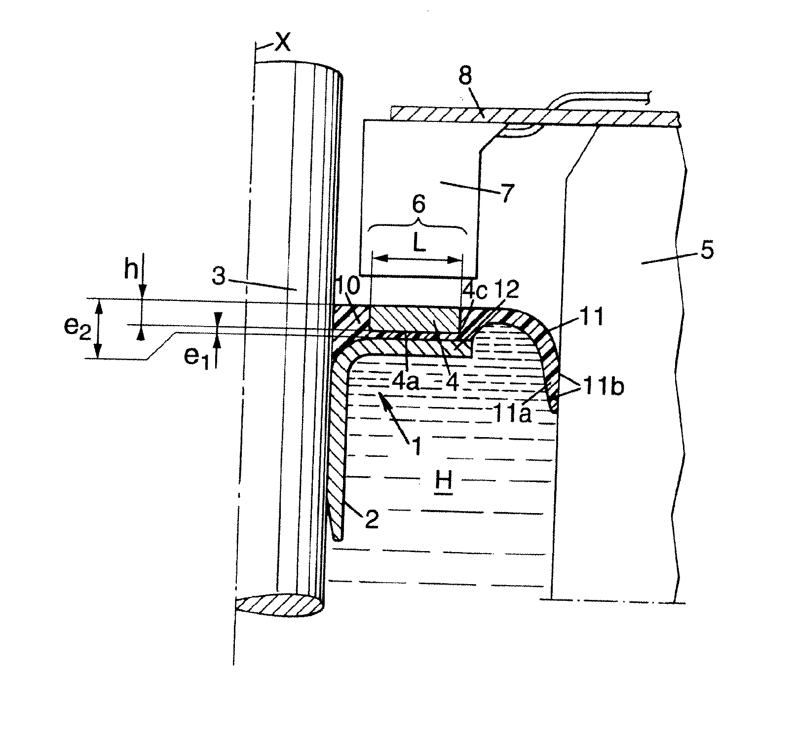
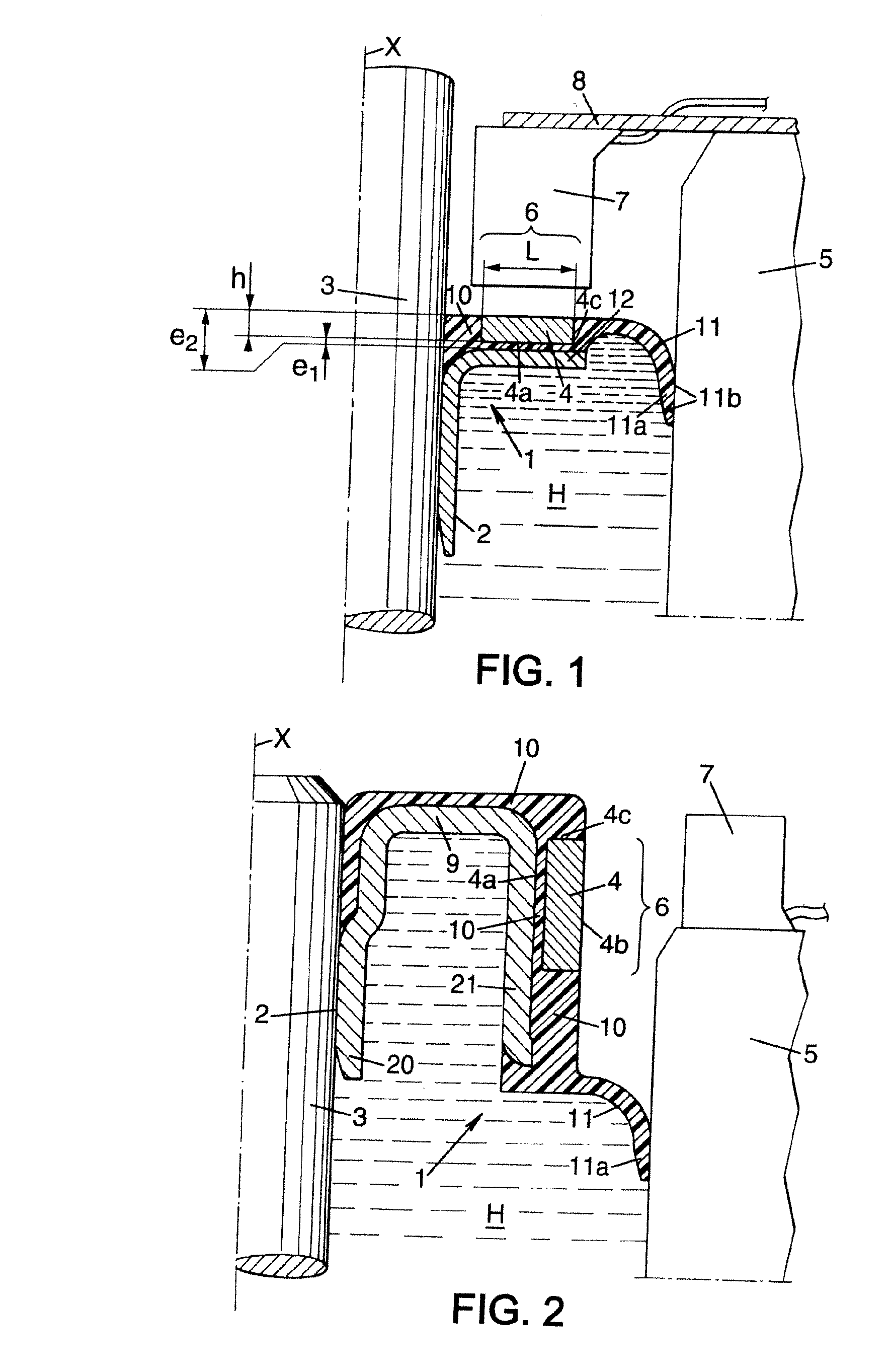
[0078]FIG. 2 shows a second embodiment, similar to the first one, that is to say having a sealing lip 11 integrally formed with the elastomer layer 10.
[0079] In this second embodiment, the encoding zone 6 extends longitudinally and is oriented radially towards the sensor 7. The encoding zone 6 is formed by a cylindrical tubular magnet 4 that surrounds an outer cylindrical wall of the sleeve 2 coaxial with the longitudinal axis X and is separated therefrom by a distance e1, in such a way that the encoding zone is annular and concentric with the shaft 3. Use of a one-piece tubular magnet allows the polarized marks to be positioned very precisely, but it is also possible to use several magnets.
[0080] The elastomer layer 10 covers the entire outer surface of the sleeve 2. The magnet 4 covers, with its internal cylindrical surface 4a, part of this elastomer layer 10.
[0081] The sleeve 2 has a U-shaped cross section, a first leg 20 of the U gripping the shaft 3, a second leg 21 supportin...
third embodiment
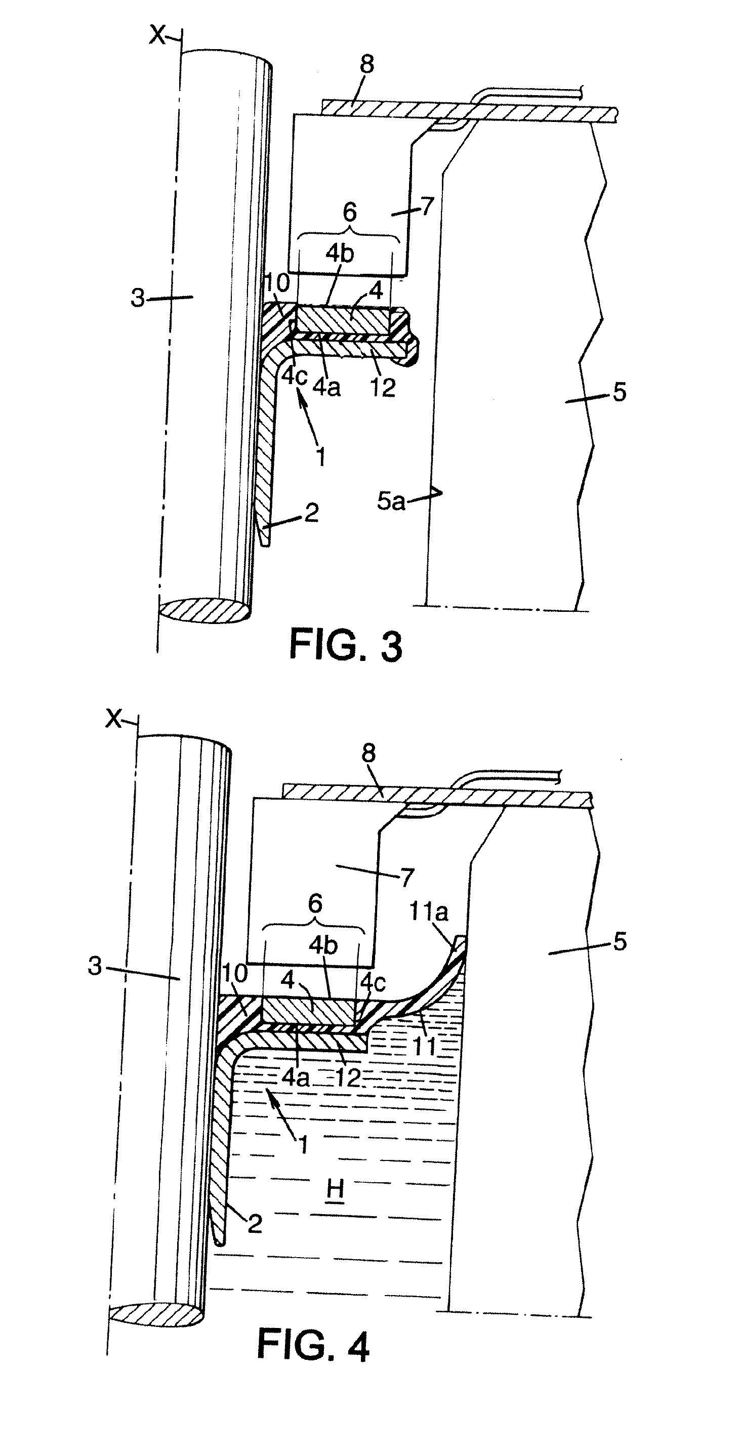
[0082]FIG. 3 shows a third embodiment, similar to the first one. In this embodiment, the sealing lip 11 has been deleted.
[0083]FIG. 4 shows a fourth embodiment, similar to the first embodiment, that is to say having a sealing lip 11 integrally formed with the elastomer layer 10. In this fourth embodiment, the lip 11 is bent towards the outside of the casing 5 filled with a liquid H.
[0084] In the embodiment shown in FIG. 5, the L-shaped sleeve 2 has a first leg 20 of the L, which grips the shaft 3, and a radial annular flange 12. The first leg 20 supports the permanent magnet 4 via the elastomer layer 10. The annular flange 12 is covered by elastomer integrally formed with the layer 10, and forming a support surface to which a PTFE (polytetrafluoroethylene) sealing lip 21 can be adhered.
sixth embodiment
[0085] In a sixth embodiment, shown in FIG. 6, the sensor 7 is placed in the internal space of the casing that contains the liquid H, against the wall 5a of the casing, and facing radially towards the shaft 3. A sleeve 2 has an L-shaped cross section with a first leg 20 of the L, which grips the shaft 3, and an annular flange 12 extending radially and concentrically with respect to the longitudinal axis X and bearing on a shoulder 30 of the shaft 3. The annular flange 12 is covered by an extension of the elastomer layer 10, which also forms a support for a lip 21.
[0086]FIG. 7 shows a seventh embodiment, similar to the first embodiment. In this embodiment, the elastomer layer 10 partly covers the inner face of the flange 12 so as to act as a support for the PTFE lip 21.
[0087]FIG. 8 shows an eighth embodiment, similar to the second embodiment. In this embodiment, the PTFE lip 21 is supported by the elastomer layer 10 and is located at the end of the second leg 21 of the sleeve 2 havi...
PUM
| Property | Measurement | Unit |
|---|---|---|
| Thickness | aaaaa | aaaaa |
| Thickness | aaaaa | aaaaa |
| Magnetic field | aaaaa | aaaaa |
Abstract
Description
Claims
Application Information
 - R&D
- Intellectual Property
- Life Sciences
- Materials
- Tech Scout
- Unparalleled Data Quality
- Higher Quality Content
- 60% Fewer Hallucinations
Browse by: Latest US Patents, China's latest patents, Technical Efficacy Thesaurus, Application Domain, Technology Topic, Popular Technical Reports.
© 2025 PatSnap. All rights reserved.Legal|Privacy policy|Modern Slavery Act Transparency Statement|Sitemap|About US| Contact US: help@patsnap.com