Power transmission apparatus for working vehicle

a technology for power transmission apparatus and working vehicles, which is applied in the direction of vehicle components, control devices, and gears, etc., can solve the problems of complicated tension adjustment work, inability to integrate with the transaxle, and complicated belt transmission mechanism adjustment work, so as to reduce costs, improve the weight balance of the power transmission apparatus, and facilitate the connection.

Inactive Publication Date: 2007-09-13
KANZAKI KOKYUKOKI MFG
View PDF12 Cites 32 Cited by
  • Summary
  • Abstract
  • Description
  • Claims
  • Application Information

AI Technical Summary

Benefits of technology

[0020] Further preferably, the gear train serving as the working apparatus drive train is disposed substantially perpendicularly to the first and second gear trains serving as the traveling drive train. Therefore, the gear train serving as the working apparatus drive train is disposed so as to be also prevented from interfering with both of the housings of the transaxles, and so as to be substantially equally distant from both of the housings of the transaxles to thereby keep a good weight balance of the power transmission apparatus.
[0021] Alternatively, preferably, in the power transmission apparatus comprising the substantially symmetric first and second gear trains to the respective transaxles, the primary drive shaft serves as the input member of the working apparatus driving power take-off device. Therefore, the gear casing is miniaturized as well as the working apparatus drive train, thereby miniaturizing the entire power transmission apparatus. Further, there exists no need of constructing a gear train serving as the working apparatus drive train, thereby reducing costs due to reduction of the number of parts.
[0022] Alternatively, preferably, in the power transmission apparatus for a working vehicle, in which the primary drive shaft, the traveling drive train and the working apparatus drive train are disposed inside the gear casing spanned between the housings of the transaxles, the input shaft of the first transaxle serves as the primary drive shaft, and the drive train portion to the second transaxle is a gear train from the primary drive shaft to the input shaft of the second transaxle. Consequently, the position of the primary drive shaft in the working vehicle becomes eccentric toward the first transaxle. This arrangement is advantageous for smoothly drivingly connecting the power transmission apparatus to the prime mover when a place of the prime mover in the working vehicle is eccentric toward the first transaxle. Additionally, input torques to the respective transaxles can be equalized by configuring the gear train to the input gear of the second transaxle so as to make the rotary speed ratio of the input shaft of the second transaxle to the input shaft of the first transaxle into 1:1.
[0023] Further preferably, the working apparatus drive train includes a gear train to the input member of the working apparatus driving power take-off device branched from an intermediate portion of the gear train from the primary drive shaft to the input shaft of the second transaxle. Due to the gear train serving as the working apparatus drive train, the working apparatus driving power take-off device can be disposed at a suitable place prevented from interfering with a drive connection mechanism interposed between the primary drive shaft and a prime mover or with the transaxles. Further, the gear train serving as the working apparatus drive train includes the portion between the primary drive shaft and the branching point of the gear train, which is shared by the gear train to the input shaft of the second transaxle, thereby preventing increase of components and expansion of the gear casing, and thereby ensuring miniaturization of the power transmission apparatus.
[0024] Further preferably, the gear train of the working apparatus drive train branched to the input member of the working apparatus driving power take-off device is disposed substantially perpendicularly to the gear train from the primary drive shaft to the input shaft of the second transaxle. Therefore, the gear train serving as the working apparatus drive train is disposed so as to be prevented from interfering with both of the housings of the transaxles and to be equally distant from the housings of the transaxles.
[0025] Preferably, in the power transmission apparatus for a working vehicle, in which the primary drive shaft, the traveling drive train and the working apparatus drive train are disposed inside the gear casing spanned between the housings of the transaxles, at least one of rotary shafts constituting the traveling drive train projects outward from the gear casing so as to be provided thereon with a cooling fan enabling cooling of both the housings. Due to the arrangement of a cooling fan, both the transaxles can be efficiently cooled with a single cooling fan, thereby reducing the number of components.

Problems solved by technology

However, the structure integrally includes neither a mechanism for transmitting power to the transaxles nor the working apparatus driving power take-off device.
One reason why the mechanisms for transmitting power from the prime mover to the transaxles and to the working apparatus driving power-take off device, disclosed in each of U.S. Pat. No. 5,127,215 and International Publication No. 97 / 15764, are difficult to be integrated with the transaxles is that they are belt transmission mechanisms.
Additionally, the belt transmission mechanism requires complicated work for adjusting a tension of the belt which varies because of variation of humidity or for another reason.
In the case that the belt is used for transmitting power to the pair of left and right transaxles, the tension-adjusting work is further complicated because the power transmission efficiencies to the respective transaxles have to be equalized.

Method used


Image

  • Power transmission apparatus for working vehicle
  • Power transmission apparatus for working vehicle
  • Power transmission apparatus for working vehicle

Examples


Embodiment Construction

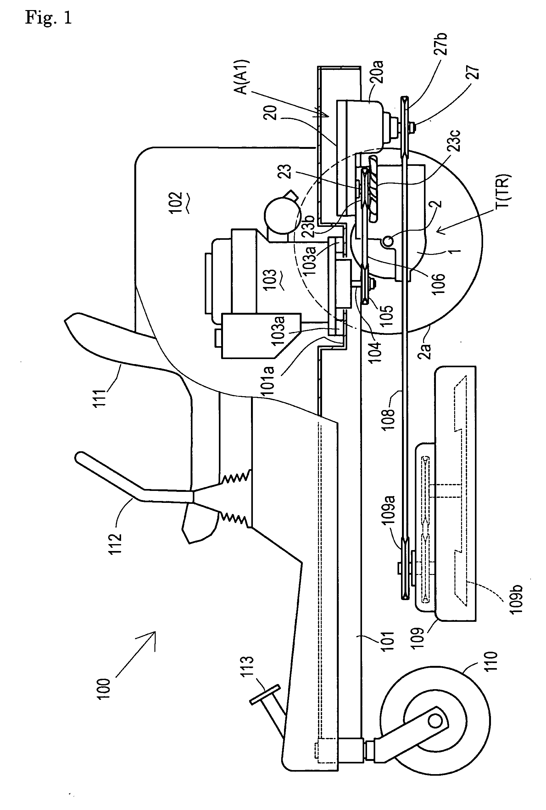
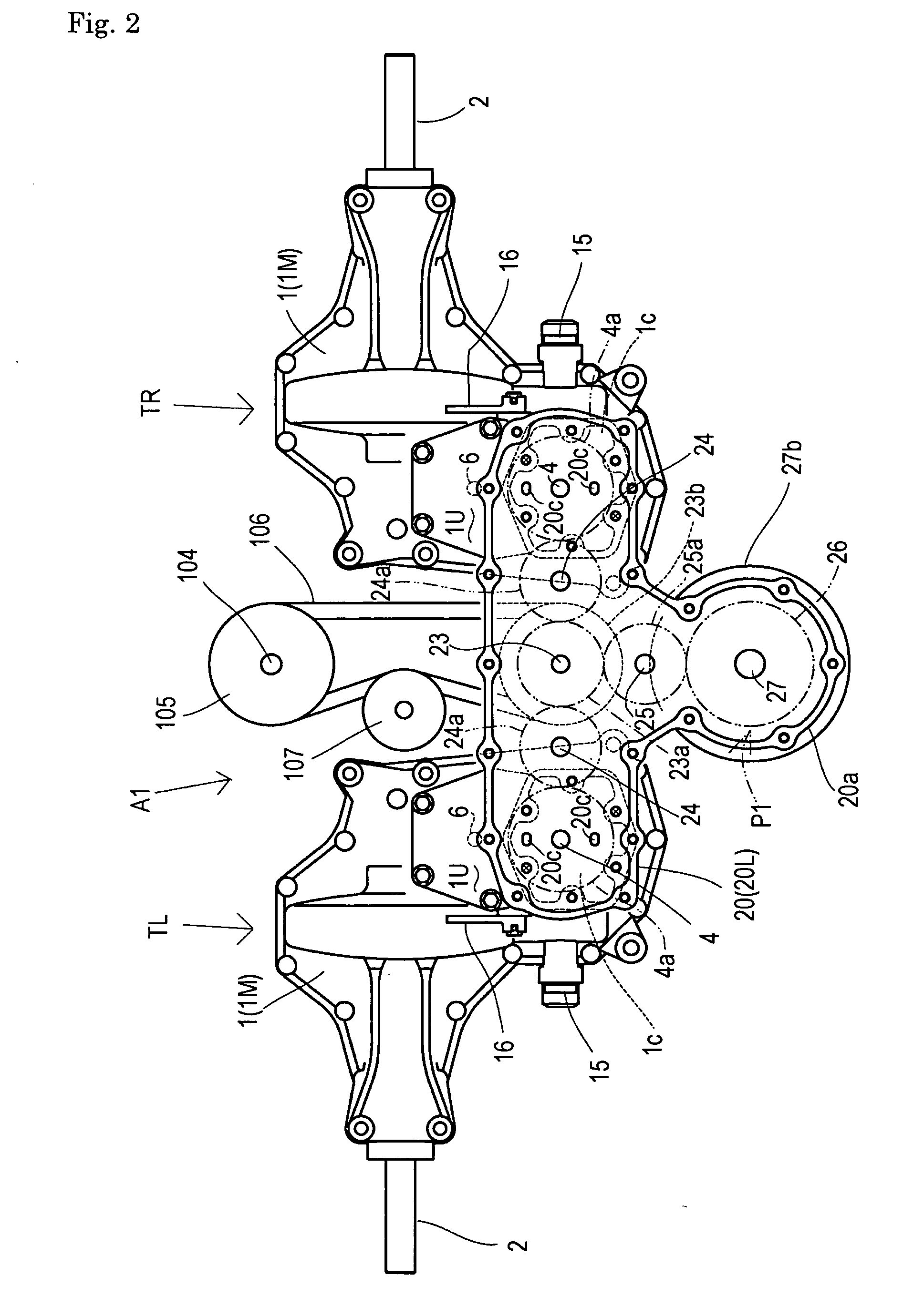
[0057] Power transmission units A1 to A4, B, C1, C2, D and E, serving as embodiments of a unified power transmission apparatus (hereinafter, referred to as a “power transmission unit”) according to the present invention, will be described.

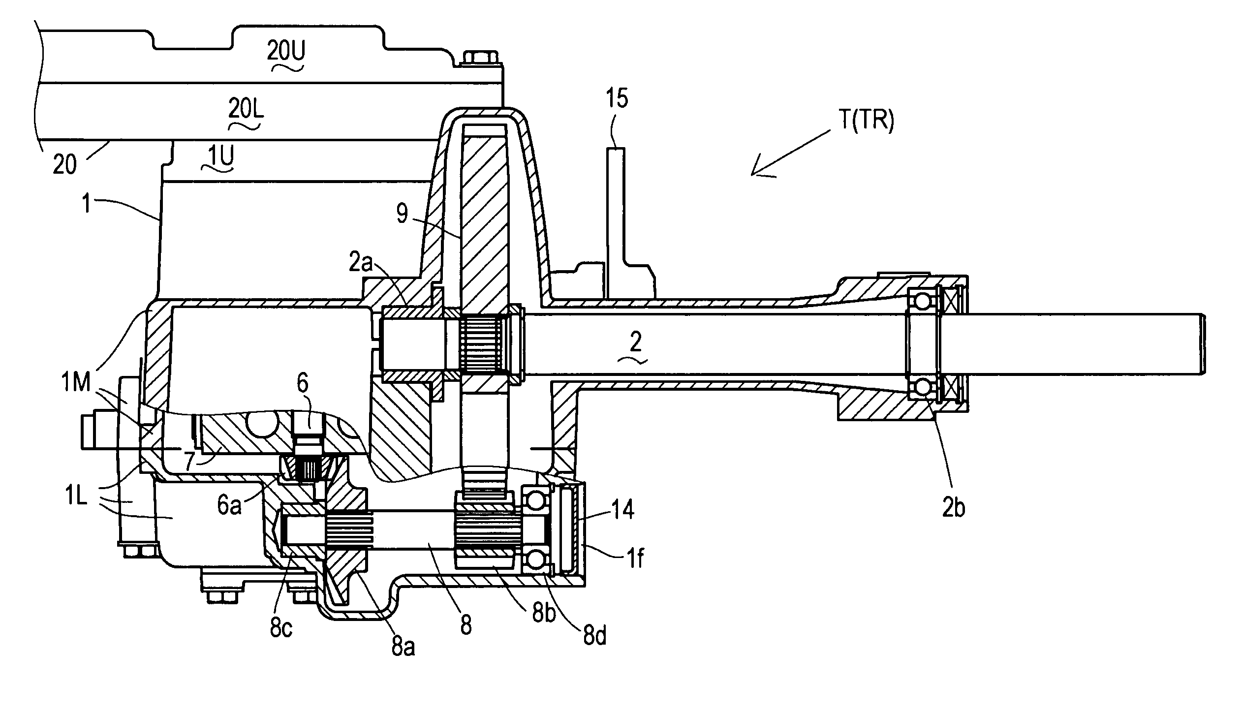
[0058] In a common structure shared among all these power transmission units, a pair of left and right symmetric transaxles TL and TR (generally named as “transaxles T”) include respective housings 1, and a gear casing is spanned between housings 1. A working apparatus driving power take-off device including a clutch is disposed in (or in continuous connection to) the gear casing. Further, the gear casing incorporates a primary drive shaft drivingly connected to a prime mover, a traveling drive train from the primary drive shaft to the respective transaxles, and a working apparatus drive train from the primary drive shaft to an input member of the working apparatus driving power take-off device. Common transaxles T are adapted to all the embodimen...


PUM


Abstract

A power transmission apparatus for a working vehicle according to the present invention comprises: substantially symmetrically disposed first and second transaxles each of which includes an input shaft and a housing supporting a single axle; and a working apparatus driving power take-off device including an input member. A gear casing is spanned between the housings of the respective transaxles. A primary drive shaft is disposed in the gear casing so as to be drivingly connected to a prime mover. A traveling drive train is disposed in the gear casing so as to drivingly connect the primary drive shaft to the input shafts of the respective transaxles. A working apparatus drive train is disposed in the gear casing so as to drivingly connect the primary drive shaft to the input member of the working apparatus driving power take-off device.

Description

BACKGROUND OF THE INVENTION [0001] 1. Field of the Invention [0002] The invention relates to a power transmission apparatus applied to a working vehicle equipped with a working apparatus, wherein a pair of symmetric transaxles, each of which includes a single axle, and a working apparatus driving power take-off device including a clutch are unified such as to constitute the power transmission apparatus. [0003] 2. Related Art [0004] Conventionally, there is a well-known working vehicle equipped with left and right symmetric independent transaxles for driving respective left and right axles, such as pedestrian-controlled lawn mowers disclosed in U.S. Pat. No. 5,127,215 (first document) and International Publication No. 97 / 15764 (second document). This type vehicle is advantageous in miniaturization, in ensuring a large space for the working apparatus, in sharp turnability (enabling “zero-turn”, as it is called), and so on. [0005] In each of the working vehicles as disclosed in the abo...

Claims


Application Information

Patent Timeline
Patent Type & Authority Applications(United States)
IPC IPC(8): F16H37/00
CPCB60K17/105B60Y2200/223B60K17/28
Inventor IRIKURA, KOJIILDA, MASARU
Owner KANZAKI KOKYUKOKI MFG
Why Eureka
Try Eureka