Solar Cell And Manufacturing Method Therefor

a technology of solar cells and manufacturing methods, applied in the field of solar cells, can solve the problems of increasing the amount of material consumed for printing, increasing the cost of printing, and wasting resources, and achieve the effect of sufficient electrode performan

Inactive Publication Date: 2007-09-13
MITSUBISHI ELECTRIC CORP
View PDF0 Cites 132 Cited by
  • Summary
  • Abstract
  • Description
  • Claims
  • Application Information

AI Technical Summary

Benefits of technology

[0012] Thereby, a solar battery according to the present invention can be provided with sufficient performance as electrodes, while maintaining electrode material consumption under control.

Problems solved by technology

In the electrode-forming technique described above, an underlying idea is that, by printing a plurality of cycles, the cross-sectional area of the electrodes increases and the resistance decreases accordingly; however, on the other hand, the amount of material consumed for the printing increases, which has led to cost rise and wasting resources.
Moreover, because grid electrodes provided on the side of light receiving faces are formed for the purpose of only collecting electrons, the electrodes do not contribute to electric power generation at all; therefore, by reducing these portions, efficiency in the electric power generation can be contrarily improved; however, if it is intended to narrow the grid width, it will then lead the electrode resistance to increase.
Accordingly, a problem has occurred in that consumption of the electrode material further increases.

Method used


Image

  • Solar Cell And Manufacturing Method Therefor
  • Solar Cell And Manufacturing Method Therefor
  • Solar Cell And Manufacturing Method Therefor

Examples


embodiment 1

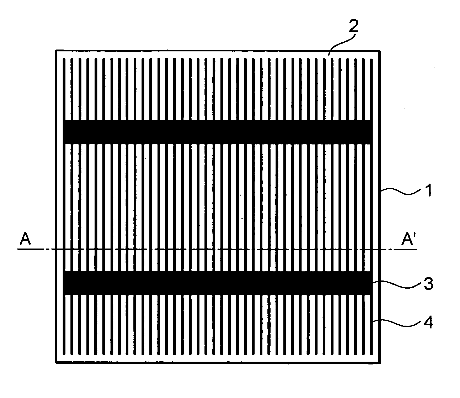
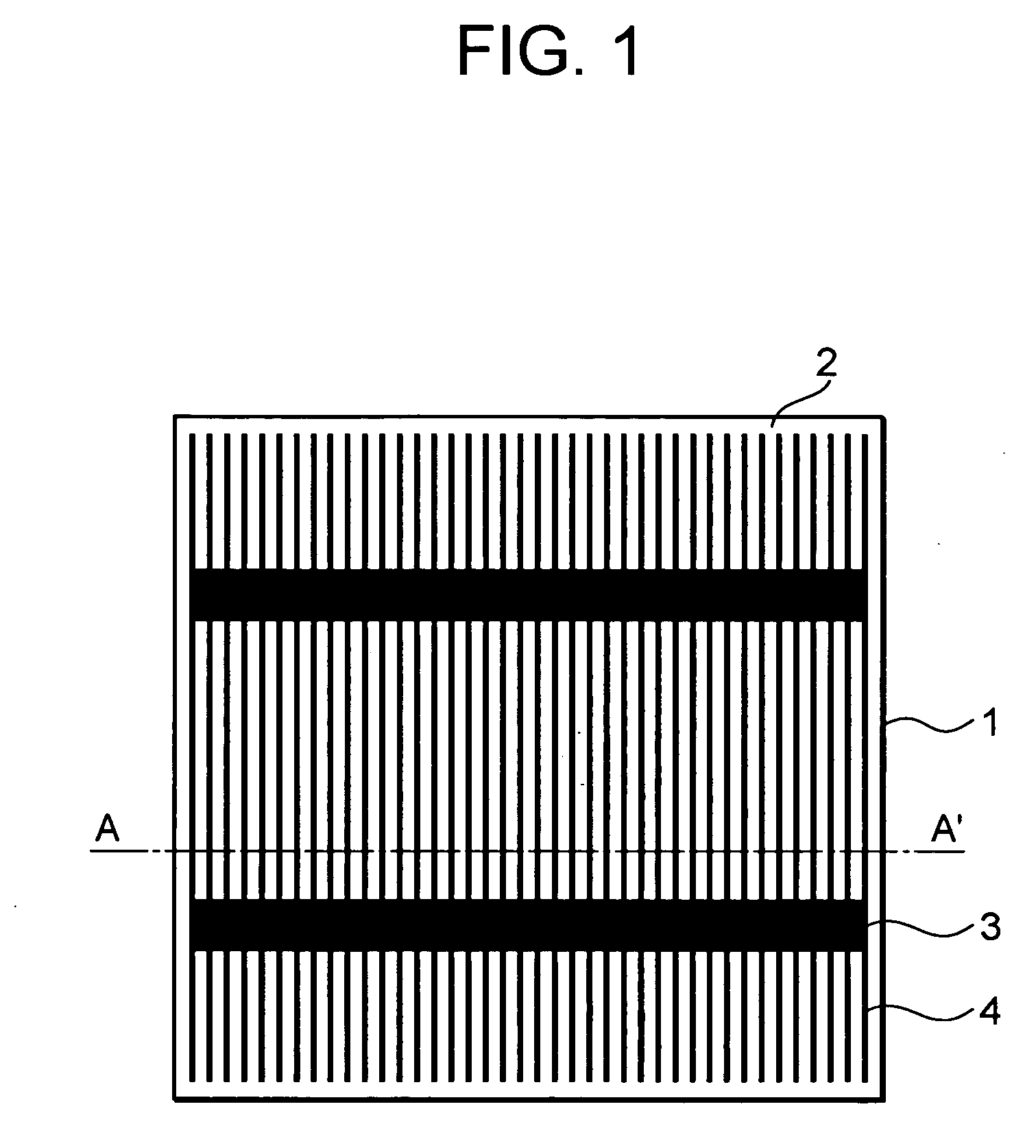
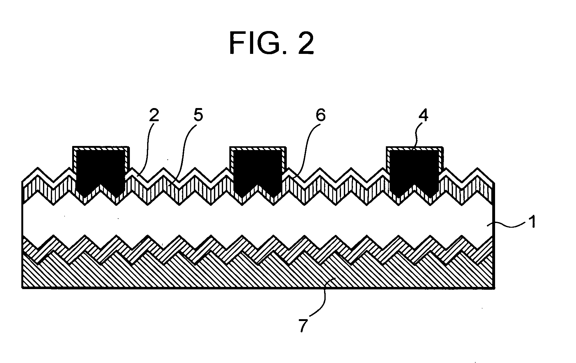
[0022] Embodiment 1 according to the present invention is explained based on figures. FIG. 1 is an arrangement view illustrating front-side electrodes of a silicon solar battery according to Embodiment 1 of the present invention. FIG. 2 is a magnified view illustrating a cross section along the line A-A represented in FIG. 1. FIG. 3 is explanatory views explaining main steps of manufacturing the solar battery according to Embodiment 1 of the present invention. FIG. 4 is front views illustrating mask patterns according to Embodiment 1 of the present invention. FIG. 5 is front views illustrating other mask patterns according to Embodiment 1 of the present invention.

[0023] When the solar battery is viewed from the front side, as represented in FIG. 1, a reflection prevention film 2 is formed on a p-type silicon substrate 1 so as to prevent light reflection and receive as much sunlight as possible, and front silver grid electrodes 4 electrically connected to front silver bus electrodes...

embodiment 2

[0042] Embodiment 2 according to the present invention is explained based on figures. FIG. 6 is front views illustrating mask patterns according to Embodiment 2 of the present invention. FIG. 7 is front views illustrating other mask patterns according to Embodiment 2 of the present invention.

[0043] Here, the structure and the manufacturing steps as a solar battery excluding the electrodes are the same as those in Embodiment 1, and the same numerals are attached to members that have equivalent functions to those having been explained in Embodiment 1.

[0044]FIG. 6 is views illustrating mask patterns used for manufacturing a solar battery according to the present invention. FIG. 6(a) is a view illustrating a first-cycle mask pattern, which is the same as the mask pattern 8 in FIG. 4(a) and FIG. 5(a) having been explained in Embodiment 1, and is composed of the bus-electrode mask pattern 9 and the grid-electrode mask pattern 10. On the other hand, FIG. 6(b) is a view illustrating a mas...


PUM


Abstract

When forming an electrode by printing several times, the cross section area of the electrode is increased and the resistance is reduced while more electrode material is required, which leads to a cost up and waste of resources. There is provided a solar cell manufacturing method for forming an electrode of a predetermined pattern by repeating printing on a substrate surface by a predetermined number of times. A mask pattern for printing the entire predetermined pattern is used at least once among the predetermined number of printings while mask patterns, each for printing a part of the predetermined pattern, are used in the other printings, thereby forming the electrode of the predetermined pattern.

Description

TECHNICAL FIELD [0001] The present invention relates to solar batteries. BACKGROUND ART [0002] In a step of forming electrodes of solar batteries, a technology is well-known in which the surface roughness of the electrodes is reduced by screen-printing electrically conductive paste onto the electrodes a plurality of cycles, so as to decrease the resistance of the electrodes (referred to as Patent Document 1). [0003] [Patent Document 1][0004] Japanese Laid-Open Patent Publication No. 103,084 / 1999. [0005] In the electrode-forming technique described above, an underlying idea is that, by printing a plurality of cycles, the cross-sectional area of the electrodes increases and the resistance decreases accordingly; however, on the other hand, the amount of material consumed for the printing increases, which has led to cost rise and wasting resources. [0006] Moreover, because grid electrodes provided on the side of light receiving faces are formed for the purpose of only collecting electro...

Claims


Application Information

Patent Timeline
Patent Type & Authority Applications(United States)
IPC IPC(8): H01L31/00H01L31/0224H01L31/0236H01L31/04H01L31/18
CPCH01L31/022425Y02E10/547H01L31/02363H01L31/1804Y02P70/50
Inventor KARAKIDA, SHOICHIMORIKAWA, HIROAKI
Owner MITSUBISHI ELECTRIC CORP
Why Eureka
Try Eureka