Methods of producing deformed metal articles

a metal article and deformation technology, applied in the field of metal billets, can solve the problems of plate products having an excessive variation in gauge, inability to achieve tight dimensional tolerances through a standardized and repeatable deformation sequence, and divergence in plate thickness

Active Publication Date: 2007-09-13
GLOBAL ADVANCED METALS USA
View PDF44 Cites 39 Cited by
  • Summary
  • Abstract
  • Description
  • Claims
  • Application Information

AI Technical Summary

Benefits of technology

[0013]It is therefore a feature of the present invention to provide a method of producing a metal having uniform fine grain size and / or textural homogeneity and optionally of dimensions sufficient for dividing into multiple slabs, or sputter targets.

Problems solved by technology

While high volume manufacturing processes offer significant cost benefits compared to batch processes, they often cannot achieve tight dimensional tolerances by means of a standardized and repeatable deformation sequence.
Imposing a predefined and consistent rolling reduction schedule on heavy slabs of high purity tantalum can result in a divergence in plate thickness with each reduction pass, and ultimately would yield plate products having an excessive variation in gauge.
Scale presents a primary factor that hinders the ability to take heavy rolling reduction when processing high volume tantalum slabs to plate since heavy reduction (e.g., true strain reduction) may represent more of a bite than the rolling mill can handle.
The separating force that would be necessary to take such a heavy bite would exceed the capability of conventional production rolling mills.
Since the processing of bulk tantalum cannot rely solely on heavy rolling reductions to reduce slab to plate, strain is not likely to be uniformly distributed throughout the thickness of the plate.
As a result, the product does not evenly respond to annealing, as evidenced by the existence of microstructural and textural discontinuities in tantalum plate as reported in the literature (e.g., Michaluk et al.
However, incorporating one or more intermediate annealing operations during the processing of tantalum plate will also reduce the total strain that is imparted to the final product.
This, in turn, would lessen the annealing response of the plate, and hence limit the ability to attain a fine average grain size in the tantalum product.
The existence or occurrence of a marbleized structure in tantalum has been deemed to be detrimental to the performance and reliability of tantalum sputtering target material and components.
The marbleized surface of tantalum can be removed by milling or etching about 0.025″ of material from each surface; however, this approach for eliminating surface marbling is economically undesirable.

Method used


Image

  • Methods of producing deformed metal articles
  • Methods of producing deformed metal articles
  • Methods of producing deformed metal articles

Examples


examples

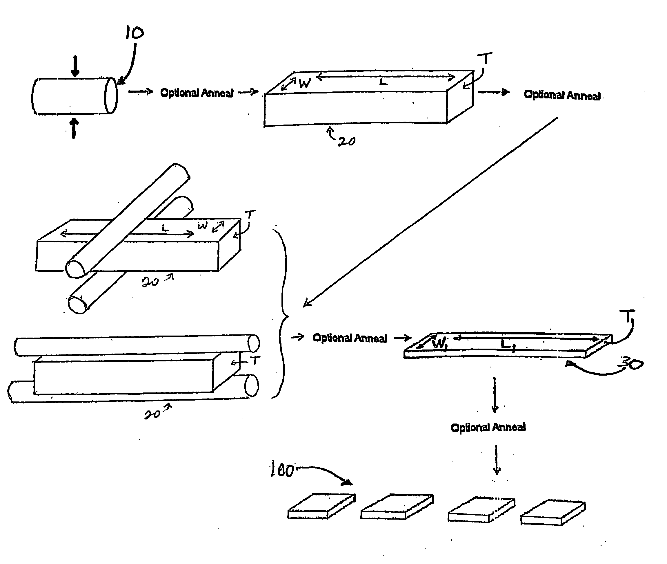
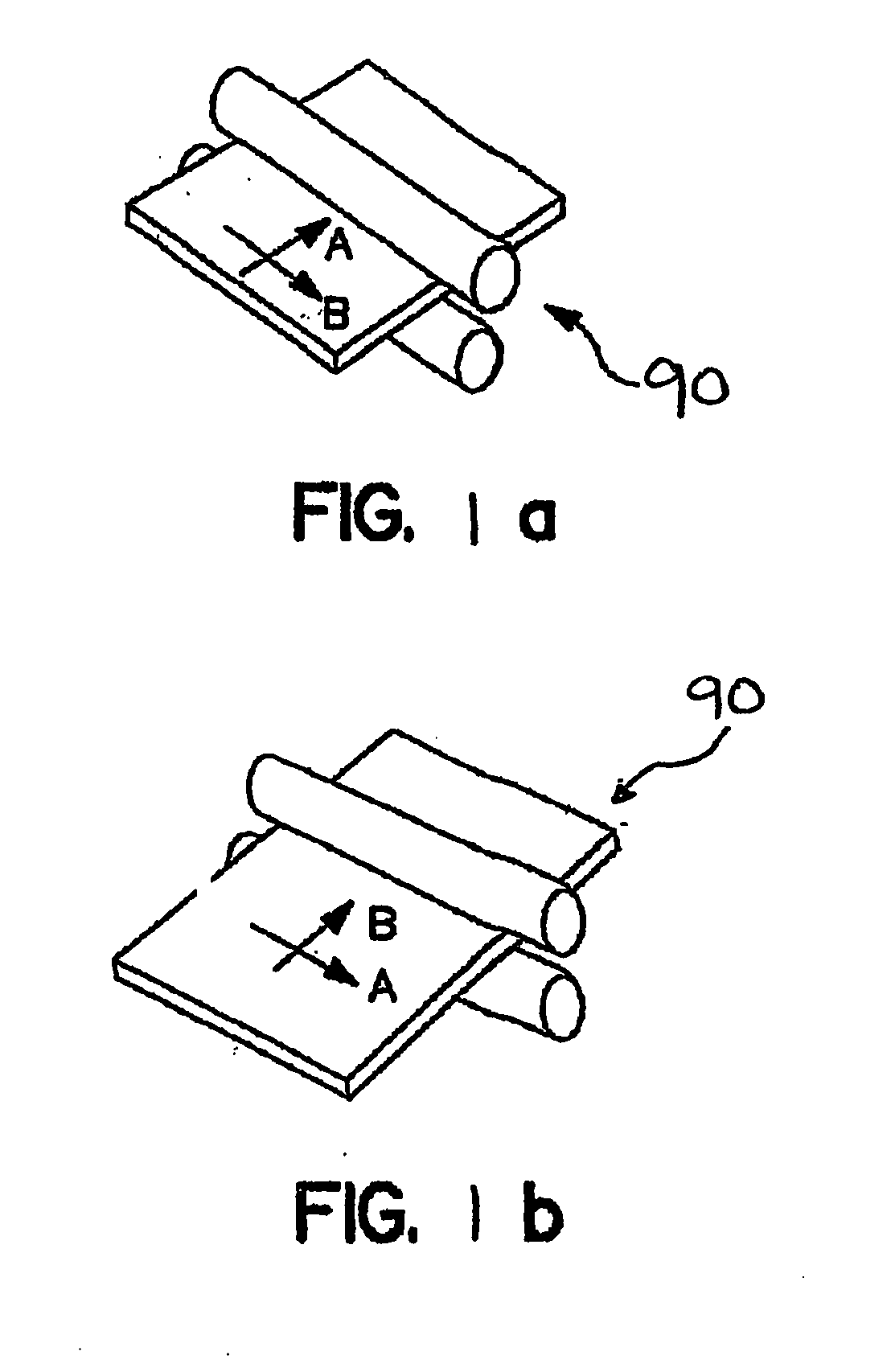
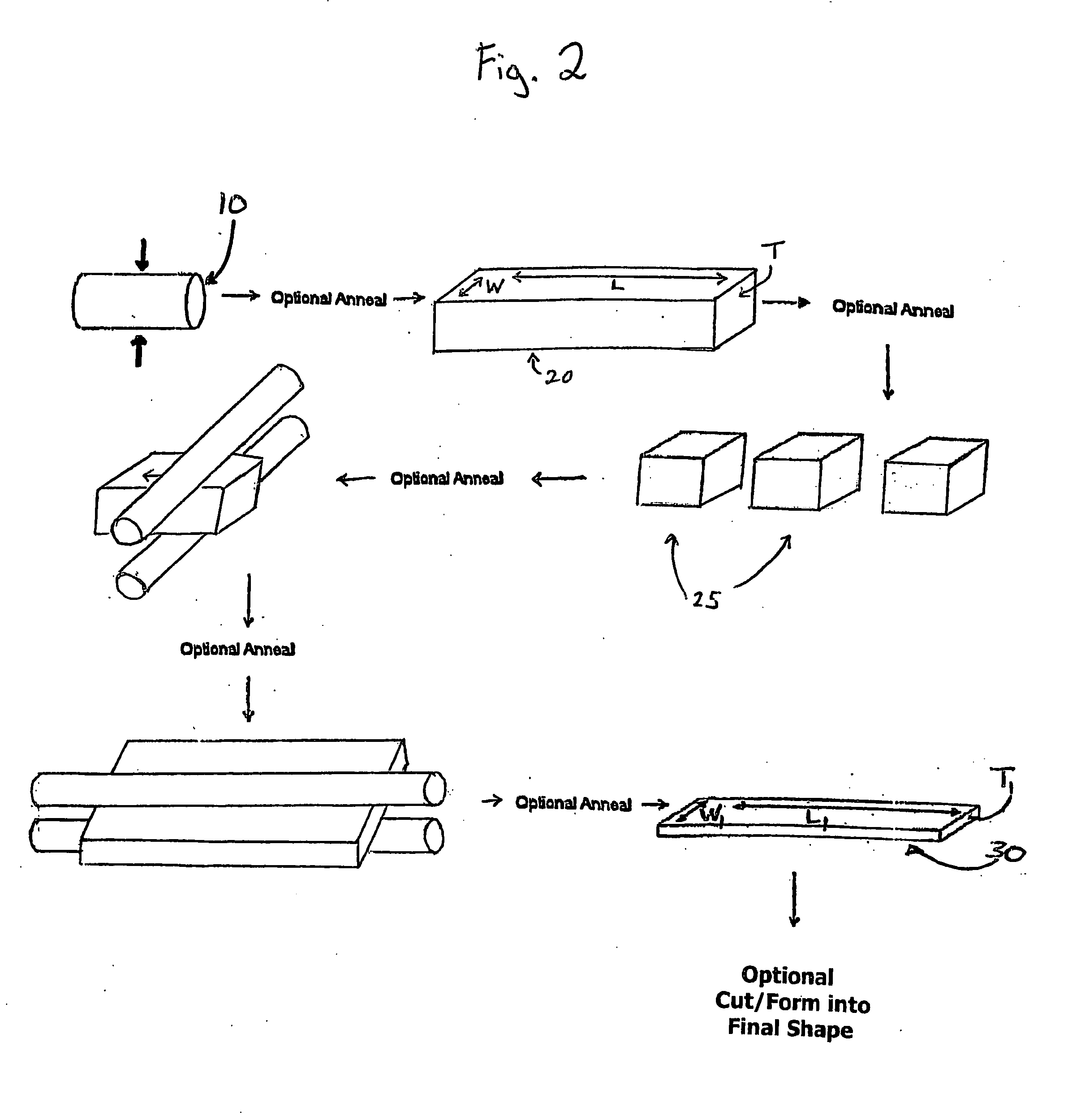
[0076]Examples: Tantalum ingots were formed into slabs using press forging steps to obtain the starting dimensions Ws=5½, Ls=as in Table 1, and Ts=5.25″ nominal. The slabs were cut into multiple slabs (up to 6) so that the cut slab length was 27 inches. The cut slabs were then machine cleaned. The slabs were then annealed at 1050° C. for 3 hrs. in a vacuum furnace. Table 1 also provides the desired final product size once it is cut from the finished plate. The slab was then subjected to a first rolling (broad side rolling) in the direction of W in FIG. 3 or A in FIG. 1a. The roll schedule for the first rolling of the various slabs is set forth in Table 2. After the first rolling, the rolled slab was cut / divided by cutting the width in half. Also, the leading edge and trailing edge that went through the rolling were trimmed off. The cut-rolled slab was then annealed for some of the samples as indicated. The “Intermediate Plate” represents the plate after the first rolling passes and ...


PUM

PropertyMeasurementUnit
diameteraaaaaaaaaa
diameteraaaaaaaaaa
temperatureaaaaaaaaaa

Abstract

A method of making metal articles as well as sputtering targets is described, which involves deforming an ingot to preferred dimensions. In addition, products made by the process of the present invention are further described.

Description

[0001]This application claims the benefit under 35 U.S.C. §119(e) of prior U.S. Provisional Patent Application No. 60 / 779,735, filed Mar. 7, 2006, which is incorporated in its entirety by reference herein.BACKGROUND OF THE INVENTION[0002]The present invention relates to metal billets, slabs, plates, rods, and sputter targets and other metal articles. More particularly, the present invention relates to a method of producing a metal preferably having a uniform fine grain size, a homogeneous microstructure, low texture banding, and / or an absence of surface marbleizing that is useful in making sputter targets and other objects.[0003]Certain observable properties of sputter targets and sputter target materials are desirable for enhancing the sputtering performance of valve metal sputter targets (See, e.g., Michaluk, “Correlating Discrete Orientation and Grain Size to the Sputter Deposition Properties of Tantalum,”JEM, January, 2000; Michaluk, Smathers, and Field, Twelfth International Co...

Claims


Application Information

Patent Timeline
Patent Type & Authority Applications(United States)
IPC IPC(8): C22F1/18
CPCB21B1/0805C22F1/18Y10T428/12993B21B1/026C22C27/02C22F1/183C23C14/3414B21B1/08
Inventor CARPENTER, CRAIG M.MAGUIRE, JAMES D.
Owner GLOBAL ADVANCED METALS USA
Why Eureka
Try Eureka