Technique for monitoring and controlling a plasma process

Inactive Publication Date: 2007-09-13
VARIAN SEMICON EQUIP ASSOC INC
View PDF22 Cites 27 Cited by
  • Summary
  • Abstract
  • Description
  • Claims
  • Application Information

AI Technical Summary

Benefits of technology

[0015] In accordance with a still further aspect of this particular exemplary embodiment, the ion sensor may be installed through a sidewall of the plasma chamber with the extractor electrode positioned near an edge of the plasma. Or, the ion sensor may be installed through an anode, and wherein the ion sensor is moveable with the anode to monitor the plasma. Alternatively, the plasma chamber may hold a wafer for processing in the plasma, and wherein the ion sensor may be positioned along a side of the wafer so that the ion sensor and the wafer share substantially the same vantage point with respect t

Problems solved by technology

Existing plasma tools often lack the capability of providing detailed real-time information (e.g., ion composition) of a plasma.
However, a Faraday cup is just a total charge counter which does not distinguish different charged particles or otherwise offer any insight of the plasma.
In addition, conventional ion sensors, such as commercial mass/energy analyzers and quadrapole mass spectromete

Method used


Image

  • Technique for monitoring and controlling a plasma process
  • Technique for monitoring and controlling a plasma process
  • Technique for monitoring and controlling a plasma process

Examples


Embodiment Construction

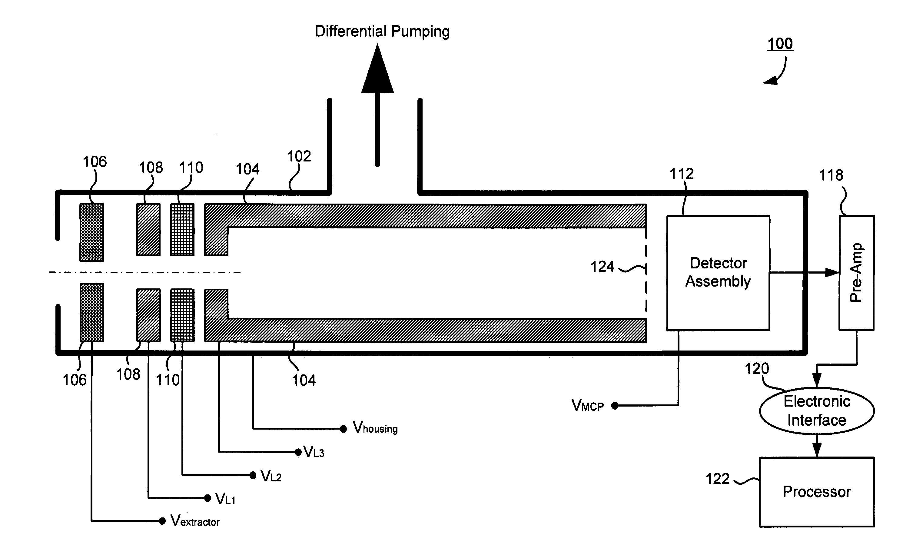
[0034] Embodiments of the present disclosure provide a number of compact designs of time-of-flight (TOF) ion sensors that are suitable for in-situ monitoring and controlling of a plasma process. These designs may employ flexible ion extraction and ion focusing techniques to measure ion composition in a plasma chamber. Each TOF ion sensor may be installed in a variety of ways in the plasma chamber and may be configured for a number of functions such as, for example, in-situ process control, chamber readiness verification, fault detection, implant dose correction, and implant uniformity measurement. The sensitivity and size of each ion sensor may allow time-resolved measurement and spatial measurement of a plasma.

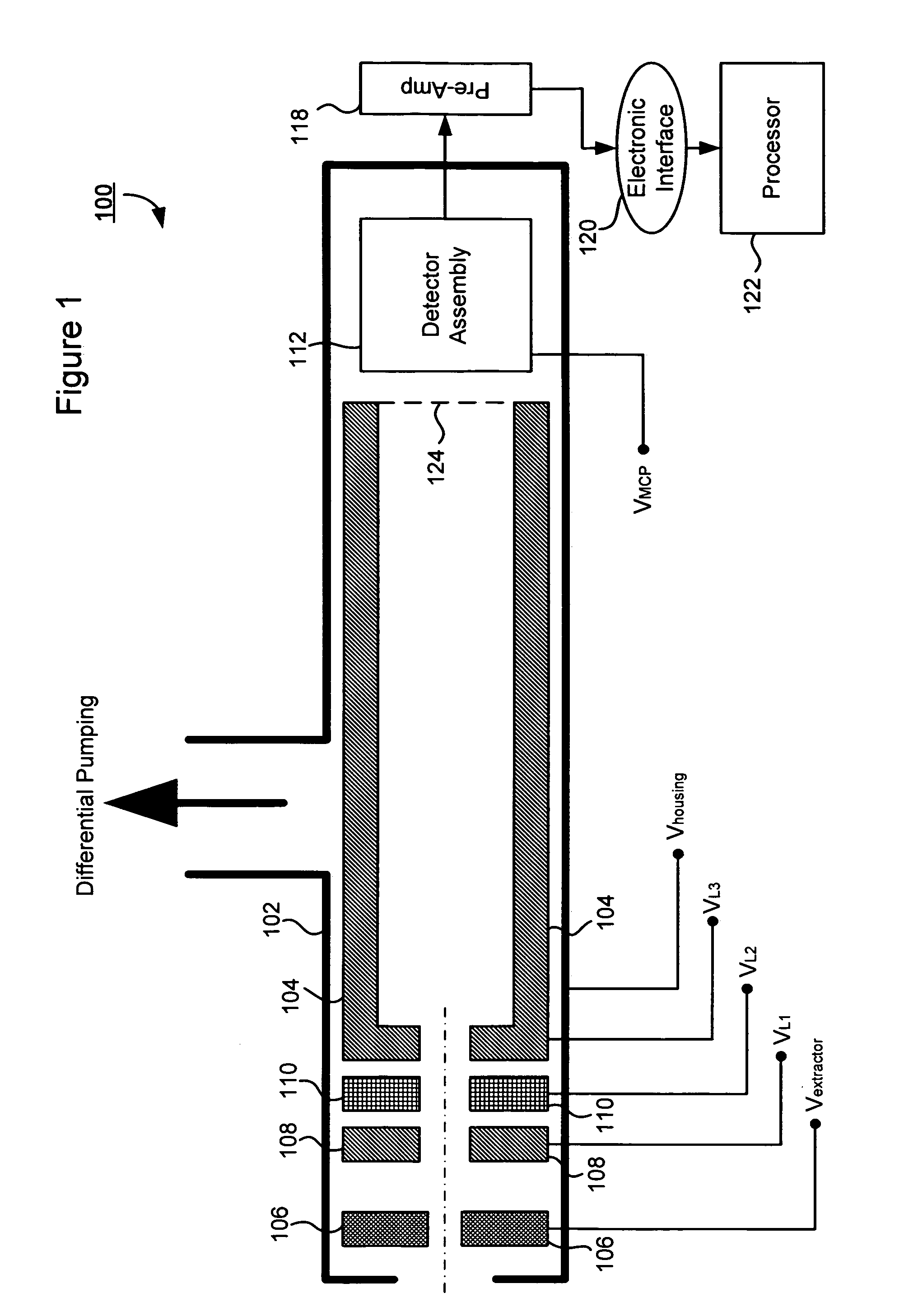
[0035] Referring to FIG. 1, there is shown an exemplary ion sensor 100 in accordance with an embodiment of the present disclosure. Ion sensor 100 may comprise a housing 102 that may be adapted for installation in a view port of a plasma chamber and may accommodate differenti...


PUM


Abstract

An in-situ ion sensor is disclosed for monitoring ion species in a plasma chamber. The ion sensor may comprise: a drift tube; an extractor electrode and a plurality of electrostatic lenses disposed at a first end of the drift tube, wherein the extractor electrode is biased to attract ions from a plasma in the plasma chamber, and wherein the plurality of electrostatic lenses cause at least one portion of the attracted ions to enter the drift tube and drift towards a second end of the drift tube within a limited divergence angle; an ion detector disposed at the second end of the drift tube, wherein the ion detector detects arrival times associated with the at least one portion of the attracted ions; and a housing for the extractor, the plurality of electrostatic lenses, the drift tube, and the ion detector, wherein the housing accommodates differential pumping between the ion sensor and the plasma chamber.

Description

FIELD OF THE DISCLOSURE [0001] The present disclosure relates generally to semiconductor manufacturing equipment and, more particularly, to a technique for monitoring and controlling a plasma process. BACKGROUND OF THE DISCLOSURE [0002] Plasma processes are widely used in semiconductor manufacturing, for example, to implant wafers with various dopants, to deposit or to etch thin films. In order to achieve predictable and repeatable process results, it is critical to closely monitor and control the plasma characteristics. For example, studies of plasma doping (PLAD) processes have shown that ion composition of a plasma may be a critical piece of information that determines dopant species, dopant depth profiles, process-related contamination, etc. The ion composition changes with PLAD process parameters such as gas ratio, total gas pressure, and discharge power. The ion composition can also change significantly depending on the conditioning status of a plasma chamber. Therefore, it is...

Claims


Application Information

Patent Timeline
IPC IPC(8): H01J49/40
CPCH01J49/40H01J37/32935
Inventor KOO, BON-WOONGGODET, LUDOVICVOURLOUMIS, VASSILIS PANAYOTISSINGH, VIKRAMFANG, ZIWEI
Owner VARIAN SEMICON EQUIP ASSOC INC
Why Eureka
Try Eureka