Optical ranging sensor and warm water wash toilet seat

a technology of optical ranging and ranging sensors, applied in wave based measurement systems, instruments, and reradiation, etc., can solve the problems of reducing the ranging accuracy, unable to utilize the entire ranging zone, and reducing the quantity of changes of output signals sb>1/b>, so as to achieve accurate obtaining an output signal and simple construction

Inactive Publication Date: 2007-09-13
SHARP KK
View PDF2 Cites 27 Cited by
  • Summary
  • Abstract
  • Description
  • Claims
  • Application Information

AI Technical Summary

Benefits of technology

[0028]An object of the present invention is to provide an optical ranging sensor capable of accurately obtaining an output signal proportional to a distance to an object to be ranged in a wide ranging zone with a simple construction without changing the dimensions of the conventional optical ranging sensor and uniforming the ranging accuracy in the entire wide ranging zone and a warm water wash toilet seat that employs the sensor.

Problems solved by technology

The conventional optical ranging sensor 100 has had a problem that, since the output signals are inversely proportional to the distance to the object to be ranged, the quantities of changes of the output signals S1, S2 became reduced as the distance to the object to be ranged is increased, and the ranging accuracy is reduced.
Therefore, it has been unable to utilize the entire ranging zone that can be detected by the optical ranging sensor, and the ranging zone has needed to be limited in uses such that a ranging accuracy is needed at a long distance.
However, the optical ranging sensor 200 has a problem that it needs the two light emitting devices 211, 212 and the light projecting condenser means 214, 215 and this leads to a complicated structure of increased dimensions in comparison with the conventional optical ranging sensor 100.
Moreover, the optical ranging sensor 200 has a problem that the ranging accuracy in the ranging zone intermediate between the proximal side and the distal side is lowered.
However, the PSD has a problem that the ranging accuracy is not constant on the proximal side and the distal side.

Method used


Image

  • Optical ranging sensor and warm water wash toilet seat
  • Optical ranging sensor and warm water wash toilet seat
  • Optical ranging sensor and warm water wash toilet seat

Examples


first embodiment

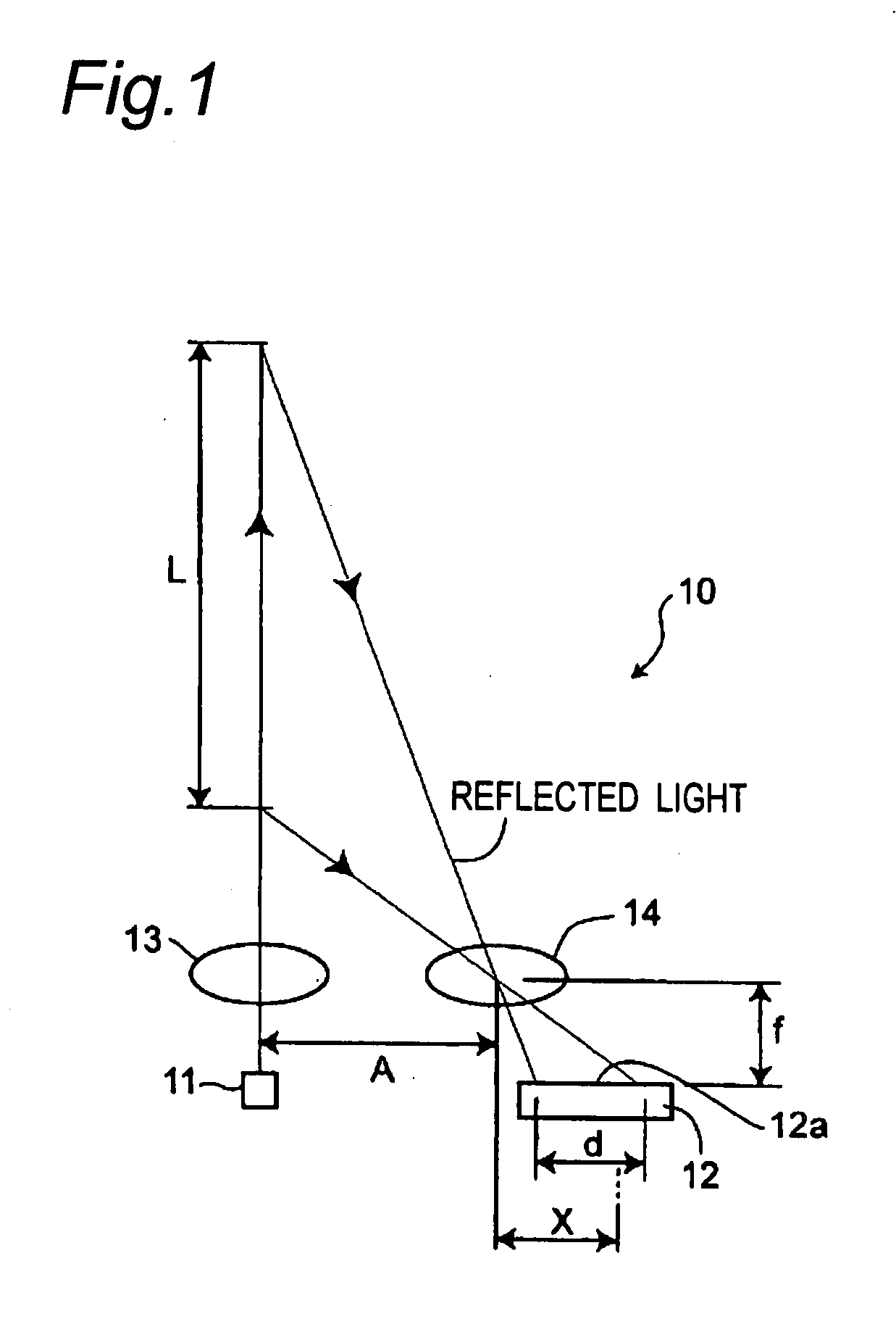
[0093]FIG. 1 is a schematic view showing the basic construction of an optical ranging sensor according to the first embodiment of the present invention.

[0094]As shown in FIG. 1, the optical ranging sensor 10 of the first embodiment includes a light emitting device 11 that emits light, a light projecting condenser means 13 that condenses light emitted from the light emitting device 11 and applies the light to an object to be ranged, a light receiving condenser means 14 that condenses the reflected light from the object to be ranged (not shown), and a light receiving device 12 that is arranged so that the light receiving surface becomes perpendicular to the optical axis of the light emitted from the light emitting device 11 and receives the reflected light condensed by the light receiving condenser means 14.

[0095]The light emitting device 11 is a light source of a light emitting diode or the like, and the light emitted from the light emitting device 11 is focused by the light projecti...

second embodiment

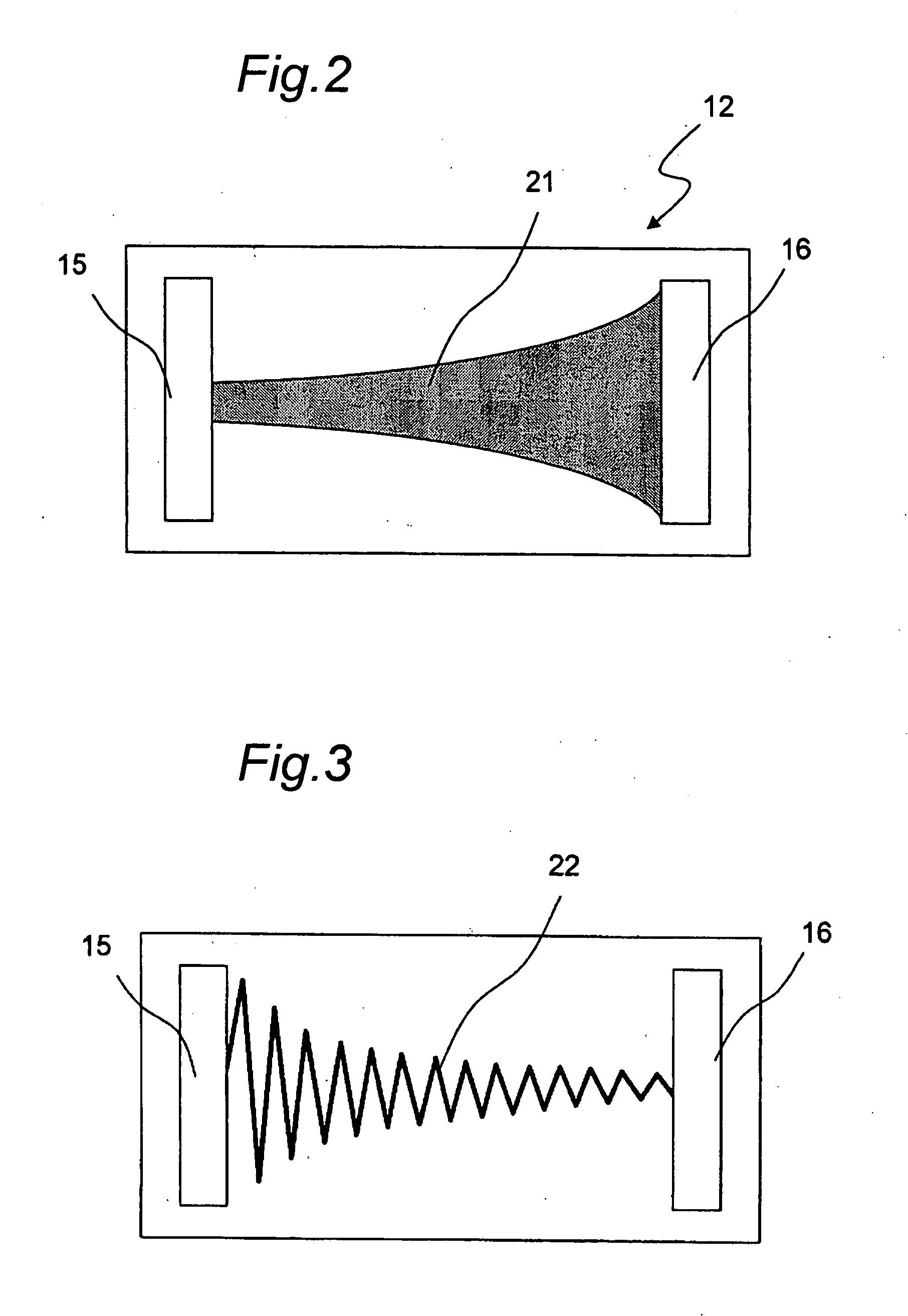
[0118]FIG. 3 shows the light receiving surface of a PSD used as a light receiving device of an optical ranging sensor according to the second embodiment of the present invention. It is noted that the optical ranging sensor of the second embodiment has the same construction as that of the optical ranging sensor of the first embodiment except for the PSD, and reference should be made to FIG. 1 with no additional description provided therefor.

[0119]As shown in FIG. 3, in the PSD of the optical ranging sensor of the second embodiment, a resistive region 22 is formed of a p− layer in the form of a zigzag bent line. The resistive region 22 is designed so that the resistance value thereof between the first and second electrodes 15, 16 is inversely proportional to the distance from the optical axis of the light receiving condenser means 14 by making the line width and the return pitch interval of the bent line constant and changing the stroke length.

[0120]Because the resistance value of the...

third embodiment

[0121]FIG. 4 shows the light receiving surface of a PSD used as a light receiving device of an optical ranging sensor according to the third embodiment of the present invention. The optical ranging sensor of the third embodiment has a construction identical to that of the optical ranging sensor of the first embodiment except for the PSD, and reference should be made to FIG. 1 with no additional description provided therefor.

[0122]As shown in FIG. 4, in the PSD of the optical ranging sensor of the third embodiment, a resistive region 23 is formed of a p− layer in the form of a zigzag bent line. The resistive region 23 is set so that the resistance value thereof between the first and second electrodes 15, 16 is inversely proportional to the distance from the optical axis of the light receiving condenser means 14 by making the line width and the stroke length of the bent line constant and changing the return pitch interval.

[0123]In the PSD of the optical ranging sensor, a light spot sh...


PUM

PropertyMeasurementUnit
electric chargeaaaaaaaaaa
resistanceaaaaaaaaaa
stroke lengthaaaaaaaaaa

Abstract

A light receiving device 12 that receives reflected light condensed by a light receiving condenser means 14 has two first and second electrodes 15, 16 provided on a light receiving surface at prescribed intervals along a baseline that connects a light emitting device 11 with the light receiving device and a resistive region 21 provided between the two electrodes. An electric charge generated at the incident position of light incident on the light receiving surface of the light receiving device 12 becomes a photo current and outputted from the first and second electrodes 15, 16 via the resistive region 21. The resistance value of the resistive region 21 of the light receiving device 12 is distributed so as to be roughly inversely proportional to a distance from the optical axis of the light receiving condenser means 14 to the incident position of a light spot on the light receiving surface.

Description

CROSS-REFERENCE TO RELATED APPLICATIONS[0001]This nonprovisional application claims priority under 35 U.S.C. §119(a) on Patent Application No. 2006-050103 filed in Japan on Feb. 27, 2006 and on Patent Application No. 2006-341598 filed in Japan on Dec. 19, 2006, the entire contents of which are hereby incorporated by reference.BACKGROUND OF THE INVENTION[0002]The present invention relates to optical ranging sensors and more particularly to an optical ranging sensor that detects a distance to an object to be ranged by projecting light onto the object and receiving reflected light and a warm water wash toilet seat that employs the sensor.[0003]As shown in FIG. 14, among conventional optical ranging sensors that detect a distance to an object is a ranging sensor that projects light from a light emitter onto the object, receives diffuse reflected light as spot light by a light receiving device 102 and detects the distance to the object on the basis of the position of the spot light (refe...

Claims


Application Information

Patent Timeline
Patent Type & Authority Applications(United States)
IPC IPC(8): G01N21/86G01V8/00
CPCG01S17/48
Inventor ISHII, KENTAROHOHKUBO, ISAMUYAMAGUCHI, AKIFUMI
Owner SHARP KK
Why Eureka
Try Eureka