Method for automatic calibration of automatic transmission

a technology of automatic transmission and automatic transmission, which is applied in the direction of mechanical equipment, vehicle sub-unit features, transportation and packaging, etc., can solve the problems of reducing the risk of performing a calibration, and slowing down the transmission power-up. , to achieve the effect of promoting more optimal operation of such vehicles, improving fuel economy, and optimising the performance of automatic transmissions

Active Publication Date: 2019-05-14
VOLVO LASTVAGNAR AB
View PDF18 Cites 3 Cited by
  • Summary
  • Abstract
  • Description
  • Claims
  • Application Information

AI Technical Summary

Benefits of technology

[0002]This is advantageous in optimising the performance of automatic transmissions, especially for trucks, semi-trucks, road trains and the like, but may also be used in other vehicles.
[0003]Advancements in transmission technology allows for more and more effective implementations of automatic and semi-automatic transmissions in vehicles which assist in promoting more optimal operation of such vehicles. This aid in improving fuel economy, reducing the time spent accelerating or decelerating to a desired speed, and reducing fatigue in drivers who can focus on the road instead of the operation of the transmission. Automatic and semi-automatic transmissions have lately also been introduced into heavier vehicles such as trucks, semi-trucks, road trains and the like, and made feasible as a result of improvements to these transmissions.
[0005]JP2004084890A discloses storing the characteristics of an automatic transmission electronic control unit to prevent behavioural change of the transmission when parts are replaced, substituting the variation characteristics of the previous part with an inputted variation characteristic.
[0013]With the method according to the disclosure the calibration of the position detection sensor is performed automatically when required. The basic idea of the disclosure is the fact that the gearshift actuators often exhibit a different actuating position after transmission service or repair, or when the gearshift control unit was temporarily dismounted from the transmission housing. During a normal engine shut down each gearshift actuator is controlled to exhibit a predetermined actuating position. However, the gearshift actuators often have to exhibit a different actuating position for enabling assembly of the gearshift control unit with the transmission housing. Consequently, simply be registering the output signal of the uncalibrated position detection sensors upon transmission power-up, an indication that a calibration of the position detection sensors can be determined. When the registered position of the gearshift actuator is outside a predetermined expected position range of the gearshift actuator then this is a strong indication that a calibration is required. Similarly, when the registered position of the gearshift actuator is within a predetermined abnormal position range then this also is a strong indication that a calibration is required. Automatic calibration of the position detection sensors according to the disclosure improves start up times of the automatic transmission because calibration is only performed when needed, and at least not upon each transmission power-up. This calibration strategy thus improves start-up times as calibration will only be performed in certain circumstances.
[0018]According to an aspect of the disclosure, the method further comprises registering the position of at least two gearshift actuators at power-up of the transmission, and performing a calibration of the associated position detection sensor if each registered position of the at least two gearshift actuators is outside a predetermined expected position range or if each registered position of the at least two gearshift actuators is within a predetermined abnormal position range. This method results in a decreased risk for performing a calibration due to measurement errors of the position detection sensor. The position detection sensors all involve a certain level of measurement error. For example, the output signal of the sensors varies with temperature. Moreover, the output signal of sensor more or less accurately represents the true condition of the measured object, which accuracy often is defined in terms of for example + / −a certain percentage. If the decision to perform a calibration is based on the output signal of two position detection sensors instead of a single sensor, the likelihood of an unnecessary calibration is reduced due to the reduced likelihood that the output signal of both sensors simultaneously involves a sufficiently large measurement error.

Problems solved by technology

Removing or replacing the GCU is a complicated task, as it is connected to and controls the actuation of the different gears of the transmission, and in the case of vehicles which include a splitter for multiple gear levels such as e.g. a semi-truck, it also controls the actuation of the splitter.
However, this calibration strategy tends to slow down transmission power-up and the calibration is in most circumstance unnecessary.
Another calibration strategy is to manually initiate calibration after transmission service or repair but there is a risk that the service technician forgets to initiate the calibration.
This method results in a decreased risk for performing a calibration due to measurement errors of the position detection sensor.
The position detection sensors all involve a certain level of measurement error.

Method used


Image

  • Method for automatic calibration of automatic transmission
  • Method for automatic calibration of automatic transmission
  • Method for automatic calibration of automatic transmission

Examples


Embodiment Construction

[0026]Various aspects of the disclosure will hereinafter be described in conjunction with the appended drawings to illustrate and not to limit the disclosure, wherein like designations denote like elements, and variations of the described aspects are not restricted to the specifically shown embodiment, but are applicable on other variations of the disclosure.

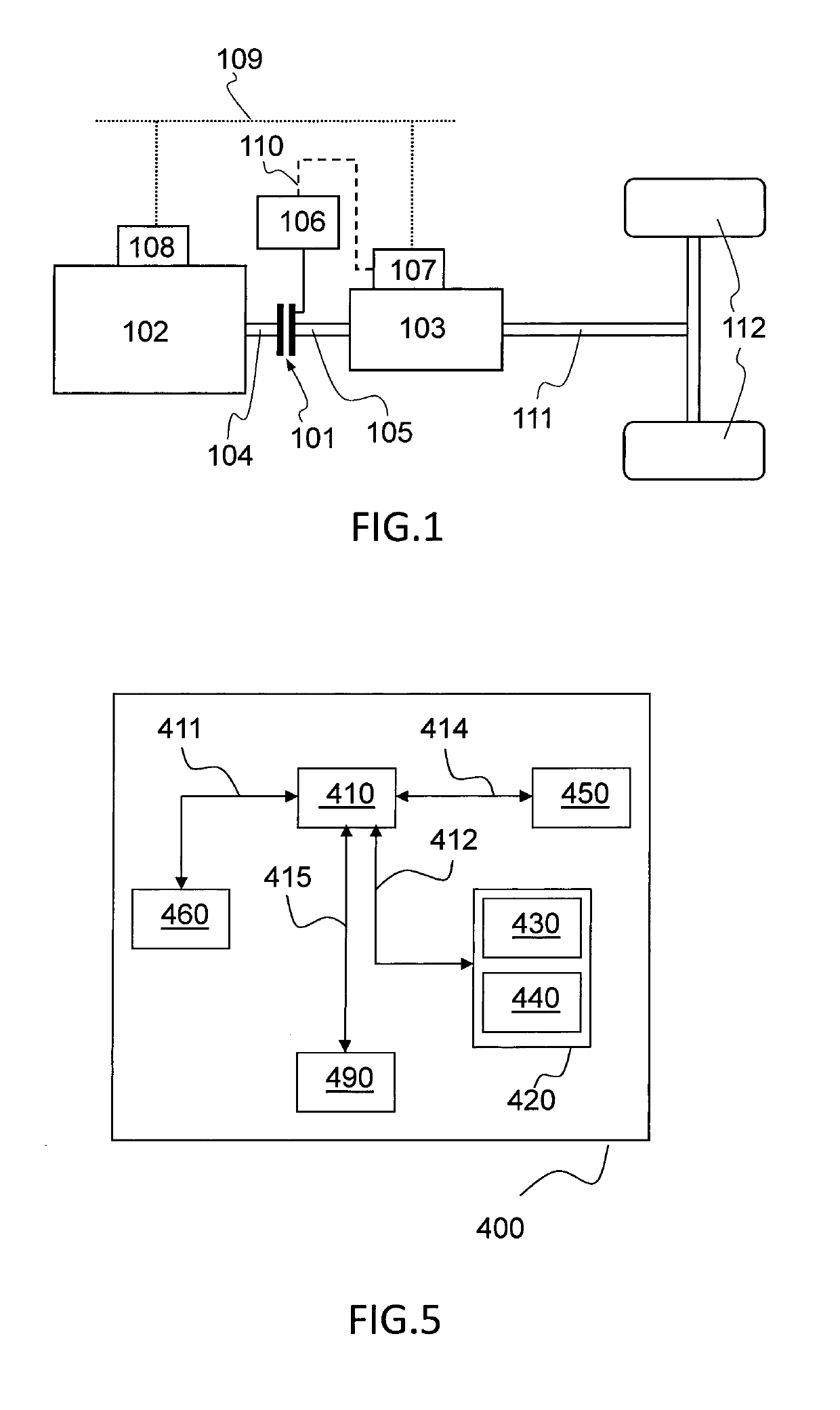
[0027]FIG. 1 shows a schematic overview of an example of a drive train in a vehicle. A master clutch 101 is situated between an engine 102 and a transmission 103, connecting a crankshaft 104 of the engine 102 to a rotatable transmission input shaft 105 of the transmission 103 of the vehicle.

[0028]A transmission output shaft 111 connects the transmission 103 with driving wheels 12 of the vehicle. When the clutch 101 is in an engaged position, it transfers torque between the crank shaft 104 and transmission input shaft 105, and when the clutch is in a disengaged position, the crank shaft 104 and input shaft 105 are decoupled from ...


PUM


Abstract

A method for automatic calibration of a position detection sensor of an automatic transmission including a gearshift actuator, the method including registering, using the position detection sensor, the position of the gearshift actuator upon power-up of the transmission; and performing a calibration of the position detection sensor if the registered position of the gearshift actuator is outside a predetermined expected position range of the gearshift actuator or within a predetermined abnormal position range of the gearshift actuator.

Description

BACKGROUND AND SUMMARY[0001]This disclosure relates to a method for automatic calibration of a position detection sensor of an automatic transmission comprising a gearshift actuator. The disclosure also relates to an automatic transmission being calibrated by such a method, as well as a vehicle comprising such an automatic transmission.[0002]This is advantageous in optimising the performance of automatic transmissions, especially for trucks, semi-trucks, road trains and the like, but may also be used in other vehicles.[0003]Advancements in transmission technology allows for more and more effective implementations of automatic and semi-automatic transmissions in vehicles which assist in promoting more optimal operation of such vehicles. This aid in improving fuel economy, reducing the time spent accelerating or decelerating to a desired speed, and reducing fatigue in drivers who can focus on the road instead of the operation of the transmission. Automatic and semi-automatic transmiss...

Claims


Application Information

Patent Timeline
Patent Type & Authority Patents(United States)
IPC IPC(8): F16H61/30B60W30/18F16H61/28
CPCF16H61/30B60W30/18054F16H61/2807F16H2061/283B60Y2304/09B60Y2400/76
Inventor KARLSSON, LARSBJERNETUN, JOHAN
Owner VOLVO LASTVAGNAR AB
Why Eureka
Try Eureka