Method of measuring a physical parameter and electronic interface circuit for a capacitive sensor for implementing the same

a capacitive sensor and physical parameter technology, applied in the direction of force/torque/work measurement apparatus, measurement of force components, instruments, etc., can solve the problems of reducing the sensitivity or gain of the electronic circuit, affecting the accuracy of the measurement, and supplying output signals such as output voltages in analogue form, so as to reduce redundancy in the electronic circuit and provide quick stabilised digital measurement signals

Active Publication Date: 2016-09-20
EM MICROELECTRONIC-MARIN
View PDF8 Cites 2 Cited by
  • Summary
  • Abstract
  • Description
  • Claims
  • Application Information

AI Technical Summary

Benefits of technology

[0014]It is thus an object of the invention to overcome the aforementioned drawbacks of the prior art by providing a method of measuring a physical parameter by means of an electronic interface circuit connected to a capacitive sensor, which can quickly supply precise output signals without any errors while also removing any voltage offset.
[0023]One advantage of the measuring method lies in the fact that at least one digital output signal for a physical parameter measurement can be quickly supplied at the electronic circuit output without any errors. The measuring method provides a good compromise between rapid changes for example of an acceleration, and the supply of measuring signals, and the reduction in noise by means of small adapting steps, in particular at the end of each conversion.
[0024]To achieve this, the measuring method advantageously uses a self-adapting algorithm to detect large acceleration changes particularly between two successive conversions or within the same conversion. After a certain number of small step measuring cycles, a decision counter determines whether there is a continual increase or a continual decrease in the digital signals in order to adapt the size of each step of the subsequent measuring cycles. Adaptation of each step to a large digital value occurs as soon as a predetermined counting threshold of a decision counter is exceeded. As soon as the decision counter determines a change of sign in the measuring cycles with a large step value, the step size of each measuring cycle is re-adapted to small steps to reduce noise.
[0030]One advantage of the physical sensor electronic interface circuit lies in the fact that it can quickly provide stabilised digital measuring signals at output owing to digital processing immediately after the charge transfer amplifier. These digital measuring signals are processed in the logic unit. A self-adapting algorithm stored in the logic unit can adapt the size of the measurement cycle adapting steps to supply adapted digital signals as a result of detection of a large change in the physical parameter measured during a measurement conversion. Two digital signals depending on positive biasing or first biasing, and on negative biasing or second biasing of the fixed electrodes of the pair of capacitors are generally supplied in the logic unit. By combining the digital signals this enables any voltage offset to be removed from the electronic circuit components.
[0031]Another advantage of the electronic interface circuit for a physical sensor lies in the fact that it can provide digital signals for each axis of a tri-axis sensor. A single amplifier, a logic unit and a single digital-analogue converter are thus provided for measuring the physical parameter on the three axes. This limits redundancy in the electronic circuit.

Problems solved by technology

These stray capacitances do not depend on the motion of the moving electrode, which consequently creates non-linearities and also lowers the sensitivity or gain of the electronic circuit.
Because of the influence of the substrate potential on the electrostatic force, this leads to a variation in the measured real force, which is applied across the common moving electrode, which is a drawback.
However, one drawback of this type of electronic circuit of EP Patent Application No. 1 835 263 is that it supplies output signals, such as output voltages, in analogue form.
This means that it is not possible to sufficiently reduce the size of the integrated components and the electrical power consumption of the integrated electronic circuit.
Although the size of the electronic components and the electrical power consumption are reduced, the aforementioned non-linearities and voltage offsets are not removed, which is a drawback.
Moreover, the stabilising time of the digital output signal for each measurement axis is relatively long, which is another drawback.
However, a large number of steps are necessary to obtain a physical parameter measuring signal at output, which is a drawback.
If an error occurs during this first measurement with a large change step in the logic unit, the final value at the end of all the measuring cycles will inevitably be erroneous, which is a drawback.

Method used


Image

  • Method of measuring a physical parameter and electronic interface circuit for a capacitive sensor for implementing the same
  • Method of measuring a physical parameter and electronic interface circuit for a capacitive sensor for implementing the same
  • Method of measuring a physical parameter and electronic interface circuit for a capacitive sensor for implementing the same

Examples


Embodiment Construction

[0036]Since various components of the sensor electronic interface circuit with differential capacitors are well known in this technical field, they will not all be explained in detail in the following description. Emphasis is mainly placed on the method of measuring the physical parameter by means of an electronic circuit which supplies digital measuring signals at output.

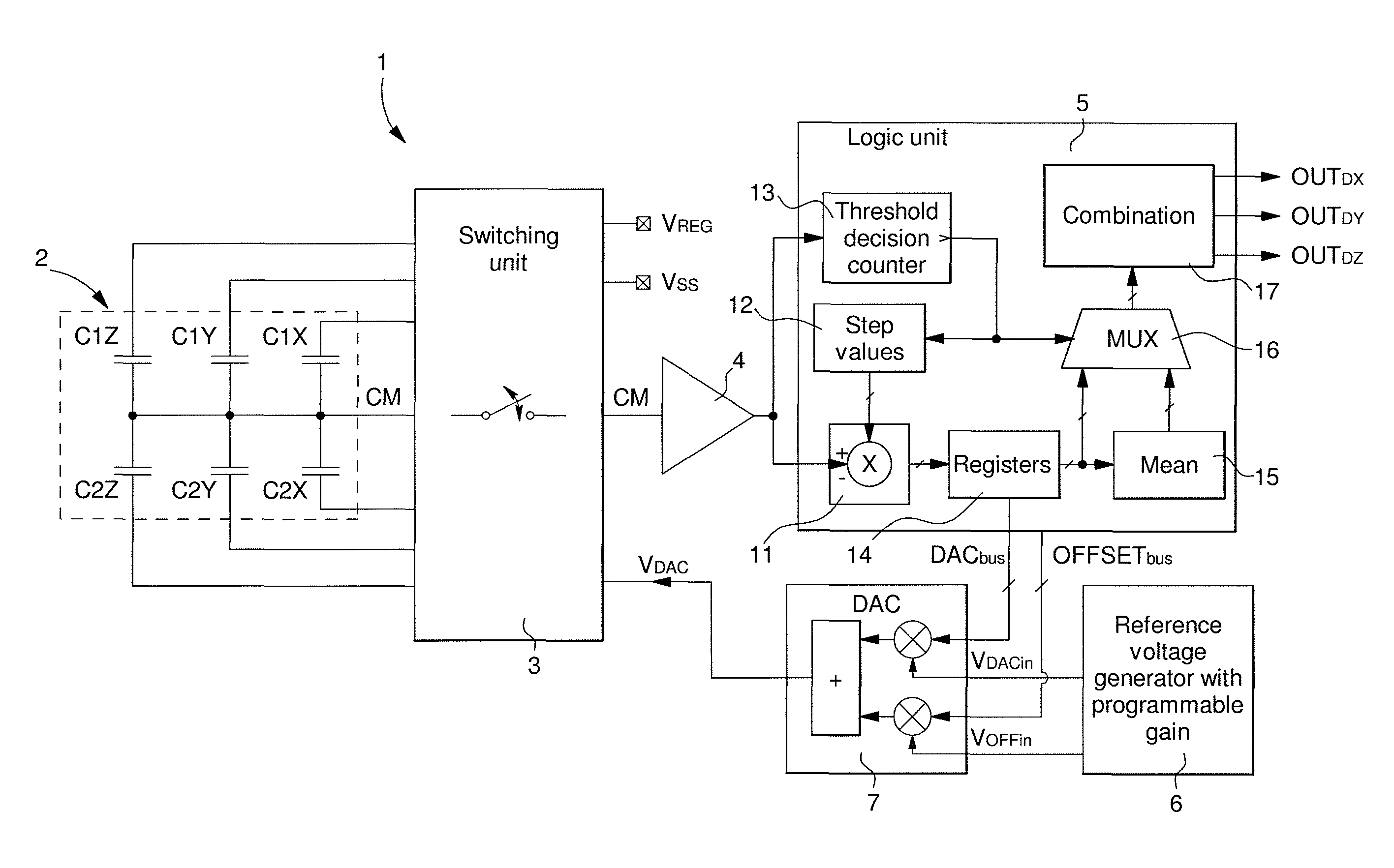
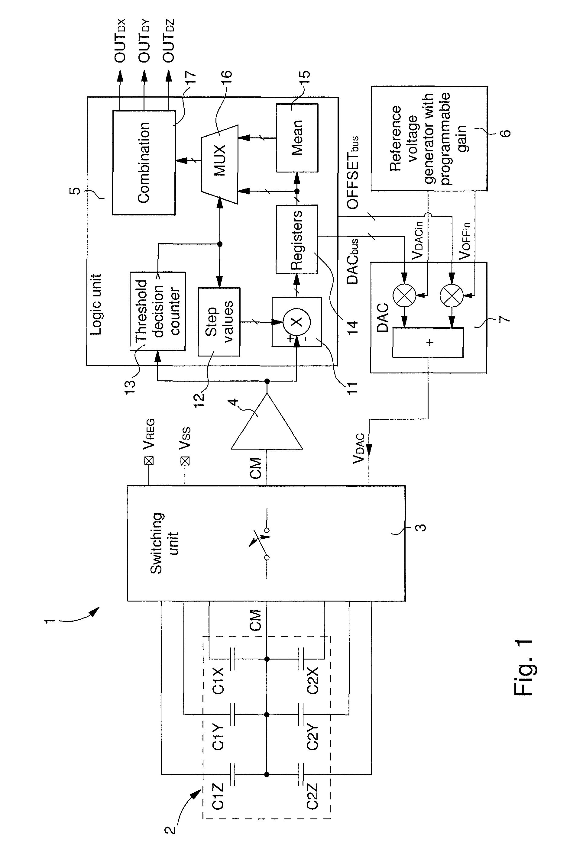
[0037]FIG. 1 shows a simplified diagram of the various components of electronic interface circuit 1 for a capacitive sensor 2 according to the invention. In this embodiment, a tri-axis capacitive MEMS sensor 2 with a single mass is connected to electronic circuit 1, although it is entirely possible to envisage connecting a tri-axis sensor with three moving masses or a single axis sensor. This capacitive sensor is thus formed of three pairs of capacitors C1X, C2X, C1Y, C2Y, C1Z and C2Z. The two capacitors of each pair are differential connected. A common electrode CM of the pairs of capacitors can move under the act...


PUM

PropertyMeasurementUnit
voltageaaaaaaaaaa
voltageaaaaaaaaaa
voltageaaaaaaaaaa

Abstract

The method is for measuring a physical parameter via an electronic circuit connected to a two differential capacitor sensor having two fixed electrodes and a common moving electrode. The circuit supplies first and second digital measuring signals. Each measuring cycle consists on biasing fixed electrodes by a first biasing and a second biasing reverse of the first biasing, alternated with biasing the electrodes by the measuring voltage based on first and second digital signals. Each conversion starts by a small step value added to or subtracted from each digital signal in each cycle. If the successive identical amplifier output states counted or counted down by a counter is higher than a threshold, a large step value is added to or subtracted from the digital signals in each cycle. Re-adaptation to the small step value occurs when a sign change is detected in the counter, until the conversion end.

Description

[0001]This application claims priority from European Patent Application No. 12151949.0 filed Jan. 20, 2012, the entire disclosure of which is incorporated herein by reference.FIELD OF THE INVENTION[0002]The invention concerns a method of measuring a physical parameter, such as an acceleration, angular speed, force or pressure, by means of an electronic interface circuit connected to a capacitive sensor.[0003]The invention also concerns an electronic interface circuit for a capacitive sensor for implementing the measuring method. The capacitive sensor is formed of at least two differential connected capacitors. A common electrode of the capacitors is capable of moving between two fixed electrodes under the action, for example, of a force in order to alter the capacitive value of each capacitor.BACKGROUND OF THE INVENTION[0004]In a simple conventional capacitive sensor design, the common electrode, which is mobile, forms part of an armature resiliently held between the two fixed elect...

Claims


Application Information

Patent Timeline
Patent Type & Authority Patents(United States)
IPC IPC(8): G01P15/125G01R27/26G01L5/16G01D5/24
CPCG01R27/2605G01D5/24G01L5/165G01P15/125G01D5/2403
Inventor GROSJEAN, SYLVAINENTRINGER, CHRISTOPHE
Owner EM MICROELECTRONIC-MARIN
Why Eureka
Try Eureka