Fluorescent Lamp for Cold Environments

a technology of fluorescent lamps and cold environments, applied in the field of fluorescent lamps, can solve problems such as reducing heat conduction

Inactive Publication Date: 2007-09-13
AURALIGHT INT
View PDF24 Cites 45 Cited by
  • Summary
  • Abstract
  • Description
  • Claims
  • Application Information

AI Technical Summary

Benefits of technology

[0010] The above-mentioned problems have been solved by a fluorescent lamp according to the invention that has the characteristics according to claim 1. Thus, the fluorescent lamp according to the invention of the type mentioned in the introduction is characterized in that the axial peripheral part of the end cap is connected to an end of the outer tube, and in that an axial spacer with low heat conductivity has a first end part that is connected to an end of the main tube, and a second end part that adjoins the outer end plane and keeps the main tube separate from the end cap in order to reduce the heat conduction from the main tube to the end cap and the outer tube. By this means, there is a minimal heat transmission from the inner fluorescent tube to the end cap located behind this and to the surrounding outer tube. In this way, a spacing function is achieved, while at the same time the transmission path for heat from the main tube to the outer tube connected to the end cap is made longer. This further reduces the heat conduction.

Problems solved by technology

This further reduces the heat conduction.

Method used


Image

  • Fluorescent Lamp for Cold Environments
  • Fluorescent Lamp for Cold Environments
  • Fluorescent Lamp for Cold Environments

Examples


Embodiment Construction

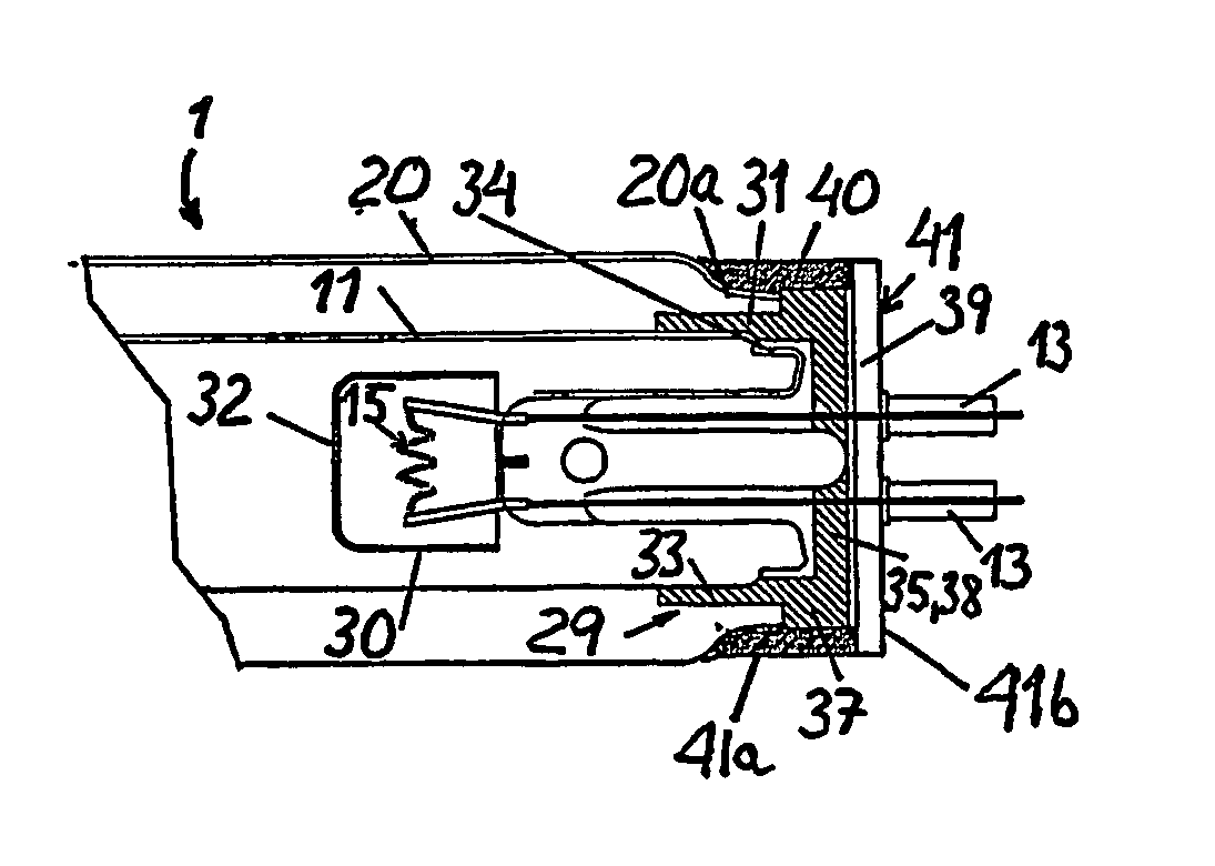
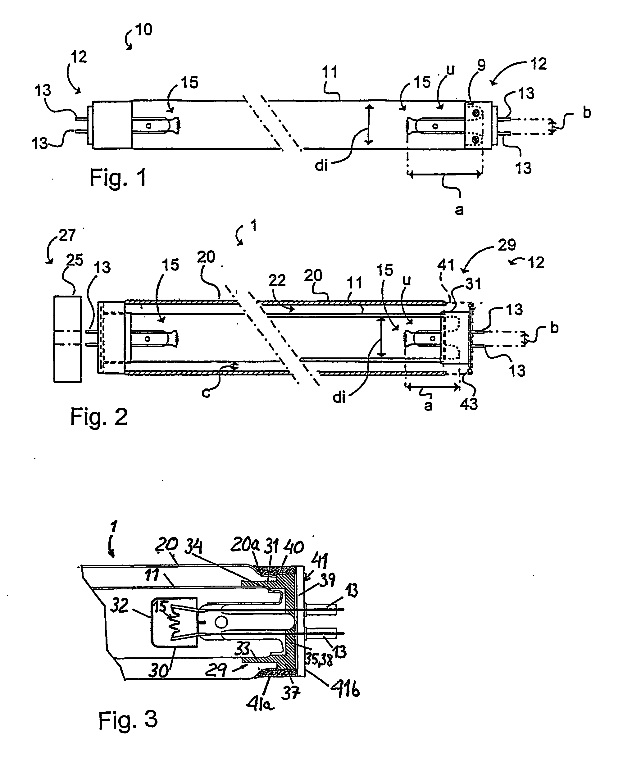
[0021]FIG. 1 shows an elongated fluorescent lamp 10 comprising a main tube 11 according to known technology. A fixing device 12 is arranged at each end, which fixing device comprises two pins 13 at a distance b apart. The fixing device 12 is intended to hold the fluorescent lamp 10 in a light fitting. The known fluorescent lamp 10 illustrated is a slimline fluorescent lamp, a so-called “T5” fluorescent lamp of the high-frequency type, designed for small spaces and very compact. The fluorescent lamp 10 comprises, in addition, two electrodes 15 provided with emitter material. One electrode 15 is placed at a distance a from the fixing device 12. The distance a and the internal diameter di of the main tube 11 define an inner space u for determining the lowest temperature zone 9 of the fluorescent lamp 10 and hence the mercury vapour pressure in the fluorescent lamp 10. The distance a is so large that the mercury condenses in an area closest to the fixing device 12, corresponding to the ...


PUM


Abstract

The invention relates to a fluorescent lamp (1) adapted for cold environments, which comprises an elongated main tube (11), fixing devices (12) at each end of the fluorescent lamp (1) for fixing the fluorescent lamp (1) in a light fitting (27), two electrodes (15) placed inside the main tube (11), a heat-insulating outer tube (20) that surrounds the main tube (11) and creates an airspace (22) between the main tube (11) and the outer tube (20). Each fixing device (12) comprises an end cap (41) with a radial part (41b), that delimits an outer end plane of the fluorescent lamp (1), and with an axial peripheral part (41a), that is connected to an end of the outer tube (20). An axial spacer (29, 31) with low heat conductivity has a first end part (33) that is connected to an end (34) of the main tube (11) and a second end part (38) that adjoins the outer end plane and keeps the main tube (11) separate from the end cap (41) in order to reduce the transmission of heat from the main tube (11) to the end cap (41) and the outer tube (20).

Description

TECHNICAL FIELD [0001] The present invention relates to a fluorescent lamp adapted for cold environments and comprising an elongated main tube, a fixing device at each end of the fluorescent lamp for fixing the fluorescent lamp in a light fitting, two electrodes provided with emitter material placed inside the main tube, a heat-insulating outer tube that surrounds the main tube and creates an airspace between the main tube and the outer tube in order to insulate the main tube of the fluorescent lamp from a cold surrounding atmosphere, with each fixing device comprising an end cap with a radial part that delimits an outer end plane of the fluorescent lamp, and with an axial peripheral part. BACKGROUND ART [0002] Fluorescent lamps are currently used to a great extent in cold environments, such as for example freezers. Known fluorescent lamps are, however, bulky and require a lot of energy. A commonly-found type of fluorescent lamp is a so-called “T8” fluorescent lamp (26 mm external d...

Claims


Application Information

Patent Timeline
Patent Type & Authority Applications(United States)
IPC IPC(8): H01J61/34H01JH01J5/48
CPCF21V17/04F21V31/00F25D27/00F21V29/15H01J61/34H01J61/70H01J5/48
Inventor AXELSSON, FOLKE
Owner AURALIGHT INT
Why Eureka
Try Eureka