Spark plug and method of manufacturing the same

Active Publication Date: 2007-09-13
NGK SPARK PLUG CO LTD
View PDF3 Cites 16 Cited by
  • Summary
  • Abstract
  • Description
  • Claims
  • Application Information

AI Technical Summary

Benefits of technology

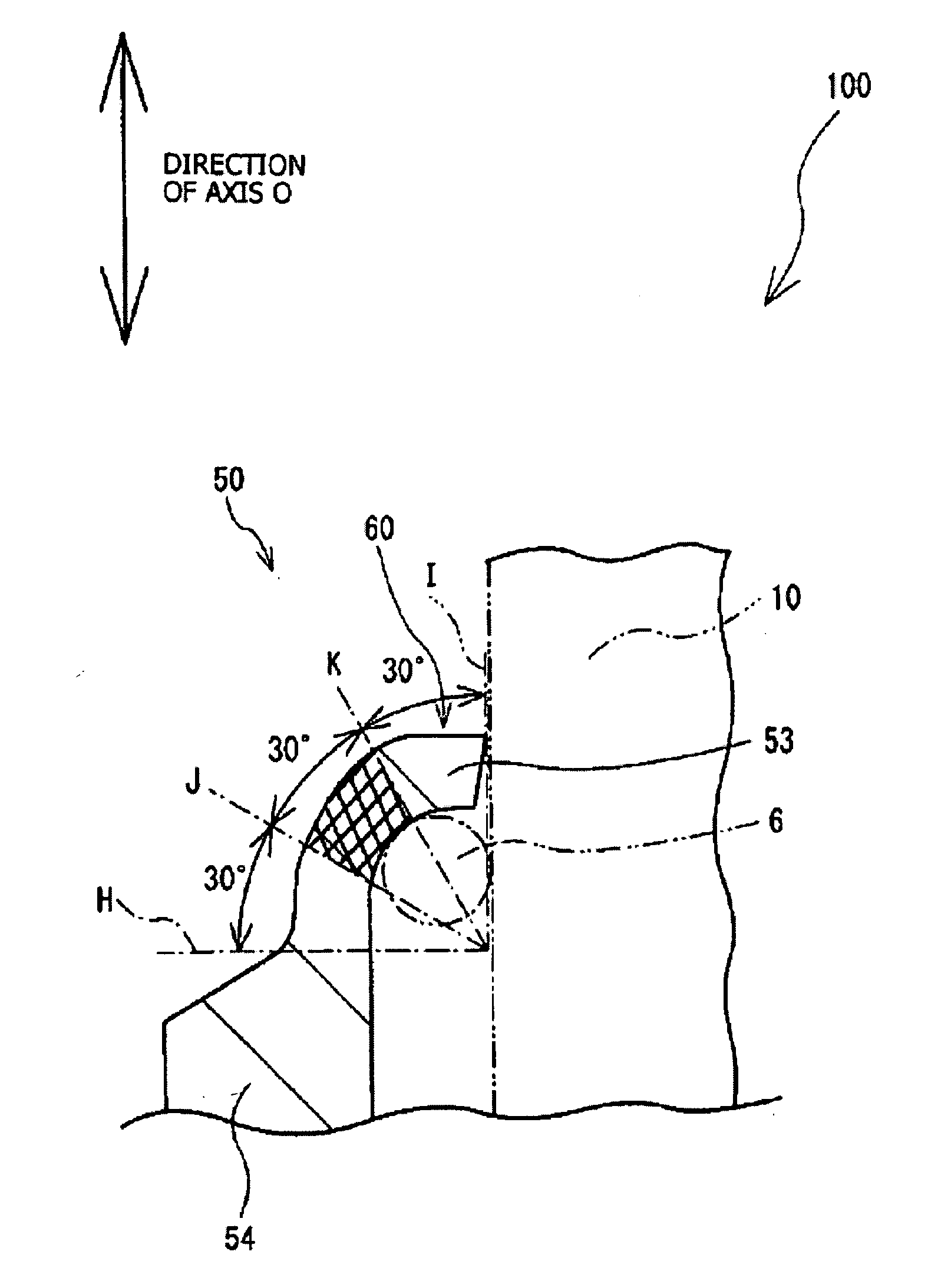
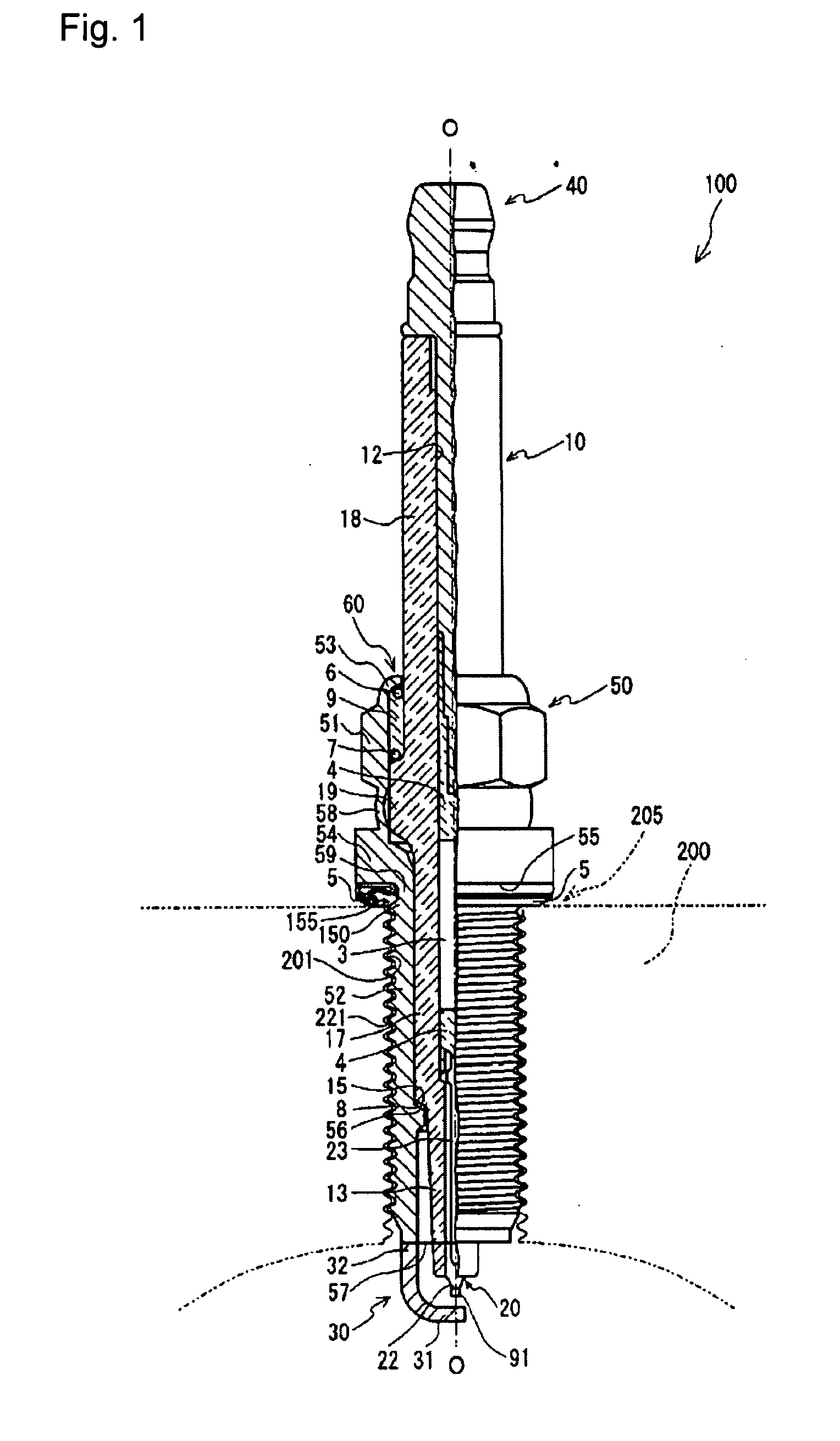
[0019]Furthermore, the crystal structure in the thread rear-end portion preferably includes martensite so that the strength of the thread rear-end portion can be greatly enhanced. As the result, cracking or rupture can be prevented effectively during tightening and fixing a spark plug to an engine head. However, if the whole of a metal housing is reinforced by martensite, machinability of the metal housing is deteriorated. Therefore, martensite preferably is selectively deposited in the thread rear-end portion. When a half cross-section of the thread rear-end portion is observed, 10% or more of the observed surface preferably constitutes a martensite phase.
[0020]On the other hand, preferably, the crimp portion of the metal housing substantially does not include a martensite phase so that machinability of the crimp portion is secured and cracking or gas leakage can be prevented. Instead of martensite, the crimp portion preferably includes at least one of an austenite phase and a pearlite phase.
[0021]In the method of manufacturing a spark plug of the invention, a c

Problems solved by technology

Thus, if the crimp portion is excessively hard, the crimp portion may rupture or cra

Method used


Image

  • Spark plug and method of manufacturing the same
  • Spark plug and method of manufacturing the same
  • Spark plug and method of manufacturing the same

Examples


Example

EXAMPLE 1

[0072]An evaluation test was conducted to confirm an effect achieved by the metal housing 50 in which the thread rear-end portion 150 has a higher hardness than the crimp potion 53. In this evaluation test, six types of metal housing were produced by means of a different partial hardening step so that their thread rear-end portions exhibit different hardness from one another. Using the metal housings, six sample spark plugs (Samples 1 to 6) were produced. In order to highlight the difference in performance, metal housings whose nominal outside diameter of the threaded portion is 10 mm (M10) were used. The other portions of the spark plug (e.g. center electrode, insulator) were the same among the samples.

[0073]However, since a ground electrode does not affect the result of the test, the samples were tested without a ground electrode bonded to the metal housing.

[0074]A steel material including carbon in an amount of 0.2 percent by weight was used as a base material in Samples...

Example

EXAMPLE 2

[0078]A further evaluation test was conducted to analyze the difference between the hardness of the thread rear-end portion and the hardness of the crimp portion. In the evaluation test, as well as in Example 1, spark plugs of Samples 7 to 17 were produced using 11 types of metal housings, each of which had a different hardness between the crimp portion and the thread rear-end portion. The metal housings were produced using base steel materials having a different carbon content from one another, or by applying a partial hardening process different from one another. Hardness of the crimp portion and the thread rear-end portion of Samples 7 to 17 is shown in the following Table 2. Three spark plugs were produced per each sample and the hardness in the table shows the average of the three spark plugs.

TABLE 2Hardness ofHardness ofthread rear-Difference incrimp portionend portionhardnessSample No.(HV)(HV)(HV)Evaluation7200410210C8140380240C9160390230A1016021050A11180380200A12200...


PUM


Abstract

A spark plug and method of manufacturing the same, the spark plug including a metal housing holding an insulator therein, the metal housing having a threaded portion formed on an outer circumferential surface of a frontward portion of the metal housing in a crimp portion formed at a rear end of the metal housing and crimping the insulator in the axial hole of the metal housing. Furthermore, the rear-end portion of the threaded portion has a hardness that is higher than that of the crimp portion.

Description

BACKGROUND OF THE INVENTION[0001]1. Field of the Invention[0002]The present invention relates to a spark plug for mounting to an internal combustion engine for igniting an air-fuel mixture, and to a method of manufacturing the same.[0003]The present invention can be applied to a device having a metal housing, such as a spark plug, a temperature sensor, and a gas sensor.[0004]2. Description of the Related Art[0005]Conventionally, an internal combustion engine uses a spark plug for ignition. An ordinary spark plug includes a center electrode whose front end portion serves as an electrode for generating spark discharge, an insulator which holds the center electrode in an axial hole thereof, and a metal housing which holds the insulator while surrounding the insulator from all radial directions. A mounting threaded portion which is formed on the outer circumferential surface of the metal housing is screwed into a mounting threaded hole in the internal combustion engine so as to mount th...

Claims


Application Information

Patent Timeline
IPC IPC(8): H01T13/04F02M57/06
CPCH01T13/20H01T21/02H01T13/36H01T13/32
Inventor SUZUKI, AKIRASUZUKI, TAKAHIRO
Owner NGK SPARK PLUG CO LTD
Why Eureka
Try Eureka