Controller

a controller and control panel technology, applied in the field of controllers, can solve the problems of time and skill, damage to the robot or machine performing the work or to the hand tool attached to the machine, the workpiece being worked on, and the time-consuming adjustment of the adjustment, so as to achieve the gain adjustment the effect of widespread use of the damping control

Active Publication Date: 2007-09-13
FANUC LTD
View PDF6 Cites 35 Cited by
  • Summary
  • Abstract
  • Description
  • Claims
  • Application Information

AI Technical Summary

Benefits of technology

[0019]According to this invention, as the present invention can be applied to damping control widely used in industry, it becomes

Problems solved by technology

However, this method has the problem that there are many limitations and it takes time and skill to accomplish the adjustment.
With this method, however, care must be taken when setting the initial value of the force control gain for adjustment; if the force control gain is set higher than the appropriate force control gain, the force control may oscillate in the first try and may cause damage to the robot or machine performing the work or to the hand tool attached to the machine, the workpiece being worked on, etc.
Conversely, if the adjustment is performed starting with a low force control gain in order to avoid such a situation, the number of tries increases, resulting in the problem that it takes time to accomplish the adjustment.
Further, in the case of a multi-axis robot, as the space where the force control is performed often contains a space of six axes, i.e., three translational axes and three rotational axes around the translational axes, if the force control gain is to be set f

Method used


Image

  • Controller
  • Controller
  • Controller

Examples


Embodiment Construction

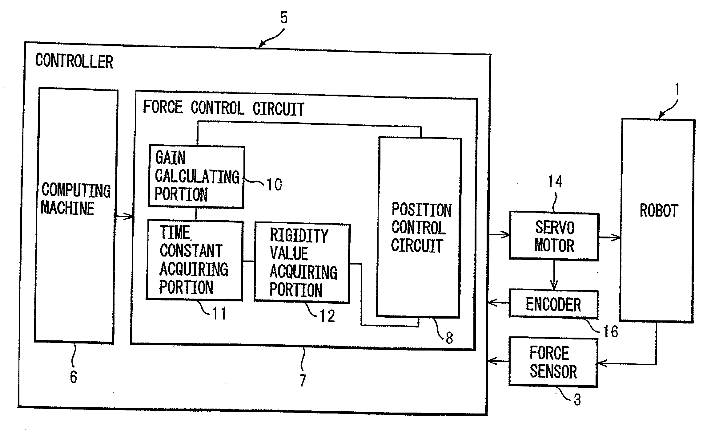
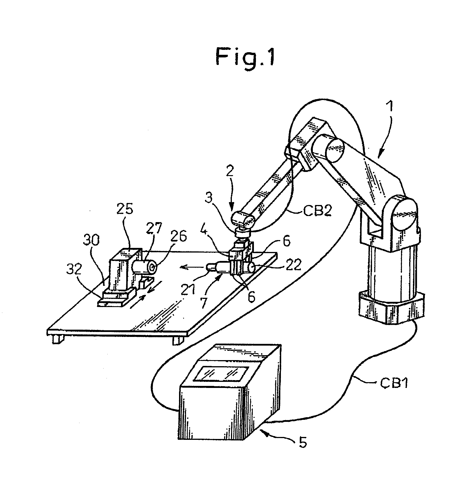
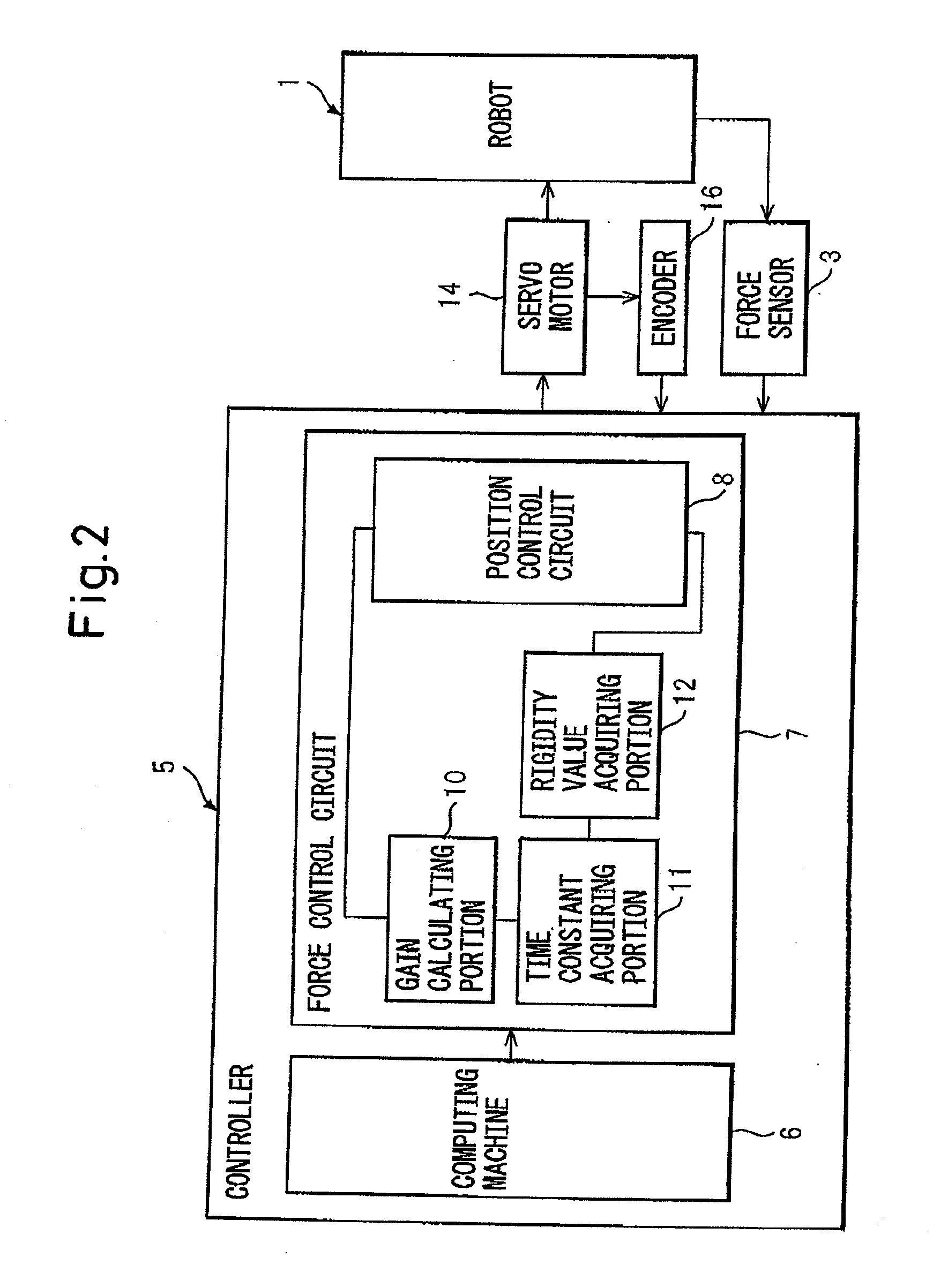
[0027]A robot controller (controller) according to the present invention will be described with reference to the drawings. FIG. 1 shows a six-axis robot as a controlled object which has three translational axes and three rotational axes. A controller for force-controlling a robot such as shown here can be classified into two main types of system: one is a system having a position control circuit connected in series inside the force control circuit, and the other is a system having a position control circuit connected in parallel outside the force control circuit. The controller according to the present invention (FIG. 2) is based on the system having a position control circuit connected in series inside the force control circuit (see FIG. 3), and is configured to be able to force-control the contact that the robot makes with the workpiece and to automatically set the force control gain based on the time constant (delay) of the position control circuit and the combined rigidity of th...


PUM


Abstract

A controller, for force-controlling a drive source of a controlled object, having a position control circuit inside a force control circuit in order to define a relative position of the controlled object to a workpiece, and a contact force occurred between the workpiece and the controlled object, the controller including a first data acquiring portion for acquiring a time constant of the position control circuit based on a position command value to the drive source and an actual position value, during operations of the controlled object; a second data acquiring portion for acquiring a rigidity value for the controlled object and the workpiece based on a force data obtained when the controlled object is brought into contact with the workpiece; and an automatic gain calculating portion for calculating a force control gain of the force control circuit from the time constant of the position control circuit acquired by the first data acquiring portion and the rigidity value acquired by the second data acquiring portion, under conditions where a time constant of the force control circuit is larger than the time constant of the position control circuit.

Description

CROSS REFERENCE TO RELATED APPLICATION[0001]This application is based upon, and claims the benefit of priority from, the prior Japanese Patent Application No. 2006-061592, filed on Mar. 7, 2006, the entire contents of which are incorporated herein by reference.BACKGROUND OF THE INVENTION[0002]1. Field of the Invention[0003]The present invention relates to a controller for force-controlling a controlled object such as an industrial robot or a machine tool that is configured to perform a task such as assembling or grinding, wherein the controller incorporates a position control circuit inside a force control circuit to force-control the controlled object.[0004]2. Related Art[0005]A controller for force-controlling a controlled object is operated to control an industrial robot or the like after setting and / or adjusting the force control gain of its force control circuit. The force-controlled industrial robot can carry out precision work that involves contacts such as fitting of precisi...

Claims


Application Information

Patent Timeline
IPC IPC(8): G05D15/00
CPCB25J9/1633G05B13/024G05B2219/39322G05B2219/42092G05B2219/40032G05B2219/41021G05B2219/39332
Inventor SATO, TAKASHIHATANAKA, KOKORO
Owner FANUC LTD
Why Eureka
Try Eureka